F940GOT-SWD-E/LWD-E
Installation, Wiring and General Specifications 2.
2-33
•
Link unit
-
NB Series
NB-RS1-AC, NB-RS1-DC
-
NJ Series
NJ-RS2, NJ-RS4
-
NS Series
NS-RS1
-
CPU in which RS-232C interface is built in NJ-CPU-B16
•
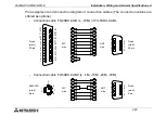
Connection diagram
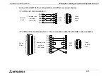
Connect the GOT and the link unit (PLC) as shown below.
< For link port connection (RS-422) >
D-sub
(male)
9-pin
Terminal
block
GOT
side
Link unit side
(PLC side)
RDA
RDB
SDA
SDB
SG
5
4
3
2
1
9
8
7
6
1
6
2
7
5
Summary of Contents for F940
Page 1: ...HARDWARE MANUAL F940GOT SWD E LWD E ...
Page 6: ...F940GOT SWD E LWD E iv Memo ...
Page 28: ...F940GOT SWD E LWD E INTRODUCTION 1 1 20 ...
Page 84: ...F940GOT SWD E LWD E Startup 3 3 18 ...
Page 88: ...F940GOT SWD E LWD E Extension Module 4 4 4 ...
Page 94: ...F940GOT SWD E LWD E Maintenance 5 5 6 ...
Page 108: ...F940GOT SWD E LWD E Additional Functions in V3 10 or later 8 8 2 ...
Page 110: ...F940GOT SWD E LWD E Additional Functions in V4 00 or later 9 9 2 ...


