F940GOT-SWD-E/LWD-E
Installation, Wiring and General Specifications 2.
2-26
2.8
Computer link port connection (MELSEC A Series)
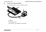
The GOT can be connected to the MELSEC A Series via a computer link unit as shown below.
•
Applicable PLC units and computer link units
< A Series >
AJ71UC24 A1SJ71UC24-R2/R4/PRF A1SJ71C24-R2/R4/PRF
A1SCPU24-R2 A2CCPUC24 (PRF)
For the communication setting for the computer link unit, refer to the F940GOT Oper-
ation Manual offered separately.
•
System configuration
R
S
232
C
R
S
422
RS232C
RS422
Programming
connector
is not used.
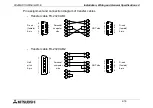
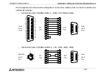
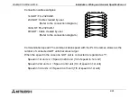
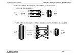
For the connection diagram, refer to the next page.
To computer link unit
Summary of Contents for F940
Page 1: ...HARDWARE MANUAL F940GOT SWD E LWD E ...
Page 6: ...F940GOT SWD E LWD E iv Memo ...
Page 28: ...F940GOT SWD E LWD E INTRODUCTION 1 1 20 ...
Page 84: ...F940GOT SWD E LWD E Startup 3 3 18 ...
Page 88: ...F940GOT SWD E LWD E Extension Module 4 4 4 ...
Page 94: ...F940GOT SWD E LWD E Maintenance 5 5 6 ...
Page 108: ...F940GOT SWD E LWD E Additional Functions in V3 10 or later 8 8 2 ...
Page 110: ...F940GOT SWD E LWD E Additional Functions in V4 00 or later 9 9 2 ...


