background image

α

2

 Simple Application Controllers

Function Blocks 6

6 - 49

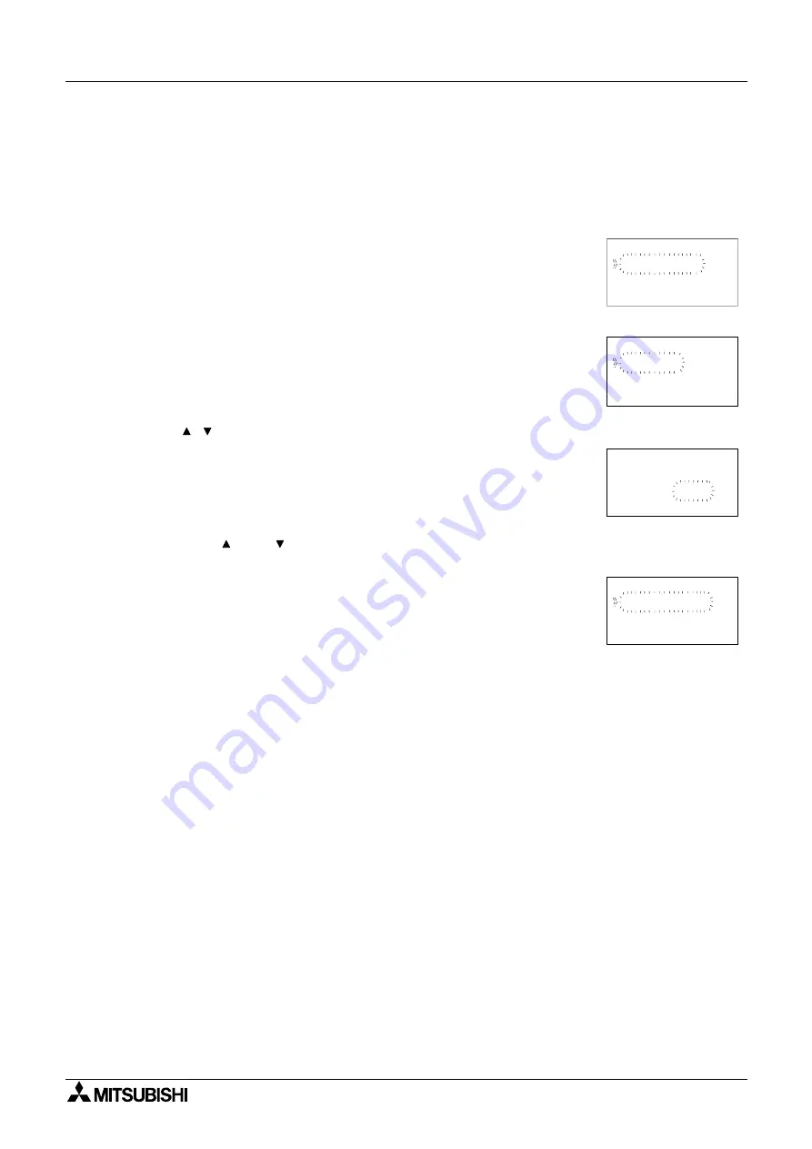
Setup of the Pulse Width Modulation Function Block directly from the 

α

Series Controller

1 ) Allocate the input pin to be used for the function block.

2 ) Press the “OK” key with the cursor in the function block. The function block edit screen is

displayed as shown.

3 ) Press the “OK” Key and enter the function block settings using the “Up and Down” keys.

4 ) Press the “OK” key with Period highlighted and the user can enter a T and t value using

the “ ,  , + and -” keys.

5 ) Press the “OK” key to return to the function block settings screen. Highlight the Duty option

using the “ 0 and  ” keys. The Duty can be entered by pressing the “OK” key. A Directset

value, Analog In or FB value can be entered.

Press the “ESC” key until the user returns to the function block diagram.

B001 : P

W

Cha ng e No
De l e t e FB

M

Se t up FB

Pe r i o d
Du t y

B001 : PWM

Pe r i

T=

s

t =

s

o d

0
0

.
.

1
0

B001 : P

W

M

D i r e c t Se t
Ana l o g I n

FB Va l u e

B001 : P

W

M

Summary of Contents for AL2 Series

Page 1: ...α2 SIMPLE APPLICATION CONTROLLER ...

Page 2: ...ntroller this manual should be read and understood If in doubt at any stage of the installation of the α2 Series Controller always consult a professional electrical engineer who is qualified and trained to local and national standards which apply to the installation site If in doubt about the operation or use of the α2 Series Controller please consult the nearest Mitsubishi Electric distributor Th...

Page 3: ...i α2 SIMPLE APPLICATION CONTROLLERS PROGRAMMING MANUAL Manual number JY992D97101 Manual revision A Date Apr 2002 α2 Simple Application Controllers ...

Page 4: ...8695 Please tick the box of your choice What condition did the manual arrive in Good Minor damage Unusable Will you be using a folder to store the manual Yes No What do you think to the manual presentation Tidy Un friendly Are the explanations understandable Yes Not too bad Unusable Which explanation was most difficult to understand Are there any diagrams which are not clear Yes No If so which Wha...

Page 5: ...perators of the completed equipment should be trained to use that product in a safe and co ordinated manner in compliance to established safety practices The operators should also be familiar with documentation which is connected with the actual operation of the completed equipment Note the term completed equipment refers to a third party constructed device which contains or uses the product assoc...

Page 6: ...α2 Simple Application Controllers iv ...

Page 7: ...ming Software Ver 2 00 2 5 3 System Menu 3 1 3 1 Menu Options Instructions 3 1 3 2 The Stop Mode 3 1 3 2 1 Top Menu 3 1 3 2 2 The Others 3 3 3 3 The Run Mode Top Menu 3 7 3 4 The Edit Menu 3 13 3 5 The Function Block Edit Menu 3 13 3 6 Option Screen Setup 3 13 3 6 1 ProgEdit 3 13 3 6 2 Change the Language Setting 3 13 3 6 3 ClockSET 3 14 3 6 4 SummerTime 3 14 3 6 5 Password 3 15 3 6 6 Serial Com 3...

Page 8: ... Keys as Inputs 4 4 4 8 The Monitor Mode 4 5 4 8 1 Monitor Update Function Block Values 4 5 4 8 2 Forcing Outputs ON OFF 4 6 4 8 3 Add Delete Function Blocks in the Monitor Mode 4 6 5 The Logic Function Blocks 5 1 5 1 The AND Block 5 2 5 2 The OR Block 5 3 5 3 The NOT Block 5 4 5 4 The XOR Block Exclusive OR 5 4 5 5 The NAND Block Not AND 5 5 5 6 The NOR Block Not OR 5 6 6 Function Blocks 6 1 6 1 ...

Page 9: ...ock 6 53 6 25 Division Block 6 54 6 26 Calculation Block 6 55 6 27 Shift Block 6 57 6 28 GSM SMS Block 6 59 6 28 1 Input Signal 6 61 6 28 2 Output Signal 6 61 6 28 3 Word Output 6 61 6 28 4 Short Message Service SMS 6 62 6 28 5 Comment Signal Number 6 62 6 28 6 Setting 6 62 6 28 7 Destination 6 62 6 28 8 SMS Setting Dialog Box 6 63 6 28 9 SMS Service Center 6 63 6 28 10 Valid Period 6 63 6 28 11 D...

Page 10: ...l through the Function Blocks by Number Section 4 6 1 7 3 7 3 3 Use the Jump Command Section 4 6 3 7 3 7 3 4 Use the NewFB command 7 4 7 3 5 Connect the Function Blocks from Right to Left Section 4 2 2 7 4 7 4 Set up the Function Block Parameters Section 4 5 1 7 5 7 5 Exit the Function Block Diagram board 7 6 8 Appendix 8 1 8 1 Associated Manuals 8 1 8 2 System Keys 8 2 8 3 System Bits 8 2 8 4 Boo...

Page 11: ...ay messages and Function Block data The α2 Series can display the state of operation and the alarm on the LCD screen as a message The values of timers and counters can be changed in RUN mode Total characters on LCD display 12 characters x 4 lines Display items Message values current or set of timers and counters analogue values etc 2 Program Input The user can program directly from the front panel...

Page 12: ... English German French Italian Spanish and Swedish 11 LCD Screen Enhanced LCD screen size allows the user to view data clearer and permits the α2 Series Controller to display bar graphs and other new intricate data representation items 12 Increased Memory The CPU memory for the new α2 Series Controller allows a maximum of 200 function blocks to create a program algorithm and contains a 5000 byte c...

Page 13: ...O0n Output n OR OR Boolean Function Block SR Set Reset Function Block OS One Shot Function Block The user can build a complex circuit in small easy steps by starting at the input and working forward in a logical manner The α2 will gather and process information and provide the necessary control for the application according to the system algorithm Each individual function block provides specific c...

Page 14: ... Number Description Signal I01 I15 Maximum of 15 Inputs are allocated for use AS i E01 E04 Maximum of 4 AS interface inputs are allocated for use Analog A01 A08 Maximum of 8 Analog inputs are allocated for use on input I01 to I08 Extension EI01 EI04 Maximum of 4 Extension inputs are allocated for use Key Name Key number Key Function OK K01 Used to enter menu options confirm data entry and manually...

Page 15: ...reprogrammed Therefore parameters within each function block dialog box can be set according to the intended application There are 38 Function Blocks available they are described in detail throughout Chapters 5 and 6 System Bit Description M01 Always ON M02 Always OFF M03 Alternate 0 5 seconds ON 0 5 seconds OFF M04 ON when Real Time Clock data error occurs M05 ON when Summer time schedule is acti...

Page 16: ...The FBD base is also known as FBD wiring area All the components should be placed only within the FBD base rectangle except for the input and output signals which can be placed in the FBD wiring area or in the Input or Output rectangles Outputs Description O01 09 Signal output A01 04 AS interface Output EO1 E04 Extension Output N01 ON Disconnected to AS interface network OFF Connect to AS interfac...

Page 17: ...software allows the user to drag and drop the desired Function Block icons onto the FBD base and construct a program The program is downloaded to the α2 controller via the AL 232CAB cable The visual on screen connections make the software easy to grasp for beginners and experienced users alike The AL PCS WIN E Programming Software is fully explained in the α Software Manual Figure 2 1 AL PCS WIN E...

Page 18: ...α2 Simple Application Controllers Function Block Programming 2 2 6 MEMO ...

Page 19: ...t has not been accepted with the OK key Note Use the ESC key to exit the option to the higher menu at times it will be necessary to press the ESC key a number of times to move to through multiple programming layers 3 2 The Stop Mode 3 2 1 Top Menu When the α2 is first turned On the Input Output Image Table will appear Press the OK and ESC keys simultaneously to move to the TopMenu If the TopMenu c...

Page 20: ... Se t upTS P r ogEd i t LANGUAGE Se t up Run S t op OK o r ESC S t op Run NoDa t a C l oc kSe t C l oc kSe t Co r r ec t C l oc kSe t C l oc kSe t Co r r ec t Eng l i s h Ge r man F r enc h I t a l i an Span i s h Sw d i s h C l oc kSe t dd m m y y y y 30 11 2001 10 45 F r i Co r r ec t s d S T Ot he r s e 2 5 9 1 5 O 1 4 8 E 1 4 A 23 E I 4 1 EO 23 1 2 3 4 ...

Page 21: ...ing is selected simultaneously depress the OK and the ESC keys to access the Top Menu Summertime Choose the preferred daylight savings time Cancel Manual On Date Type UK type US type or EU type Serial Com Choose the type of communication to be used for the right hand side serial communication port Not Use Modem GSM or Other Com Light Time Set the backlight off delay time ProgClear Completely clear...

Page 22: ...r Res e t Re s e t Sc anT i me OK o r ESC Se t up Pas swo r d D i s pPa s s Pas swo r d D i s pPas s Lev e l 1 Lev e l 2 Lev e l 3 D i s pPa s s Lev e l 1 Se t up MenuKe y MenuKey No ON Us e ESC Key Sum me r T i me Sum me r T i me Can c e l Manua l On Da t aTy pe UK Ty pe US Ty pe EU Ty pe Sum me r T i me 31 03 30 10 60mi n 3 4 Se r i a l Com L i gh t T i me P r ogc l ea r P r ogC l ea r Se t up L...

Page 23: ... i t P NCode Se t SMS GSMS t a t us Comf o r ma t S t a t i onNo L i nkB l oc k Ot he r Com Ot he r Com S t a t i onNo No 0 Ot he r Com L i nkB l oc k 0 Comf o r ma t S t a t i onNo L i nkB l oc k Ot he r Com Ot he r Com GS Remo t e ModemI n i t 01 Com mand y z ModemI n i t 0s a De l yT i me a De l yT i me a M I 5 6 7 8 Datalength Parity Stopbit Baudrate 8 bits 2400 bps None 1 bit 7 bits 4800 bps ...

Page 24: ... t SMS GSMS t a t u s GS Remo t e P NCode GSMI n i t Com mnd De l ayT i me GS Remo t e Fo r b i t Pe r mi t P I NCode Se t up Se t SMS SMSC1 SMSC2 DA1 DA2 DA3 VP GSMS t a t us S t a t us CMEE r r o r CMSE r r o r S i gSe i ng M M I 7 8 Datalength Parity Stopbit Baudrate 8 bits 2400 bps None 1 bit 7 bits 4800 bps Odd 2 bits 9600 bps Even 19200 bps Comformat 300 bps 600 bps 1200 bps ...

Page 25: ...form limited editing to FB parameters The existing programming steps cannot be modified ClockSet Set the Real Time Clock or input a daily clock adjustment LANGUAGE Choose the on screen language from English German French Italian Spanish or Swedish Others Add FB O01 OK ESC 01 In 01 Connect EO04 Adding Function Blocks or Skips to the next topic 1 2 3 Function Block Specific Changes Function Block Nu...

Page 26: ... Mon i t o r LANGUAGE Se t up Run S t op OK o r ESC S t op Run NoDa t a C l oc kSe t C l oc kSe t Co r r ec t C l oc kSe t C l oc kSe t Co r r ec t Eng l i s h Ge r man F r enc h I t a l i an Span i s h Sw d i s h C l oc kSe t dd m m y y y y 30 11 2001 10 45 F r i Co r r ec t s d S t op TS e 10 19 F r i I 2 5 9 1 5 O 1 4 8 E 1 4 A 23 E I 4 1 EO 23 1 2 3 4 ...

Page 27: ... i me Mon i t o r Res e t Res e t Sc anT i me OK o r ESC Se t up Pas swo r d D i s pPas s Pas swo r d D i s pPas s Lev e l 1 Lev e l 2 Lev e l 3 D i s pPa s s Lev e l 1 Se t up MenuKey Sum me r T i me Sum me r T i me Can c e l Manua l On Da t aTy pe UK Ty pe US Ty pe EU Ty pe Sum me r T i me 31 03 30 10 60mi n MenuKey No ON Us e ESC Key 3 4 Se r i a l Com L i gh t T i me Se t up L i gh t T i me 2m...

Page 28: ...P NCode Se t SMS GSMS t a t us Comf o r ma t S t a t i onNo L i nkB l oc k Ot he r Com Ot he r Com S t a t i onNo No 0 Ot he r Com L i nkB l oc k 0 Comf o r ma t S t a t i onNo L i nkB l oc k Ot he r Com Ot he r Com GS Remo t e ModemI n i t 01 Com mand y z ModemI n i t 0s De l ay T i me De l ay T i me De l ay M I 5 6 7 8 Datalength Parity Stopbit Baudrate 8 bits None 1 bit 7 bits Odd 2 bits Even C...

Page 29: ... r ma t GSMI n i t Se t SMS GSMS t a t u s GS Remo t e P NCode GSMI n i t Com and De l ayT i me GSRemo t e Fo r b i t Pe r mi t P I NCode Se t up Se t SMS SMSC1 SMSC2 DA1 DA2 DA3 VP GSMS t a t us S t a t us CMEE r r o r CMSE r r o r S i gS t i ng M m I r 7 8 Datalength Parity Stopbit Baudrate 8 bits 9600 bps None 1 bit 7 bits 19200 bps Odd 2 bits Comformat Even ...

Page 30: ...itor Screen in Run Mode Individual for each Function Block 1 OK ESC 01 Settings for Function Blocks Ed i t Menu P r ogS i z e Ex i t FBSe t t i n Se t B l ac k 4FB Memo r y 1 J ump MI OKEANE I EOB In B002 B003 01 In S 003 RSR P I 02 Out g up J ump Moni t o r Screen 1 2 ...

Page 31: ...vailable in Monitor Mode 3 5 The Function Block Edit Menu The Function Block Edit Menu can be entered only while in the ProgEdit or Monitor mode Move to the Function Block to edit and press the OK key when the Function Block number is flashing Setup FB Optimise variables in the Function Blocks for your application See Chapter 6 for more details on each Function Block s Options The logic functions ...

Page 32: ...the date is changed 3 6 4 SummerTime The Summertime menu will display six choices when entered Cancel Turns off the Summertime clock setting Manual On Moves the clock one hour ahead immediately and will remain ON until cancelled Date Type Set the On date Off date and Time adjustment UK Type Last Sunday of March to the last Sunday of October US Type First Sunday of April to the last Sunday of Octob...

Page 33: ...rial Com The modem function capability of the α2 allows remote monitoring via a PC and program upload download The communication must take place using the Visual Logic Software VLS and the communication must be initiated accordingly The modem connected to the α2 is initialised upon the α2 start up Dialing options from a command or specific conditions are not available Command Enter the AT command ...

Page 34: ...he same the words Verify Error will blink onscreen To Transfer a Program from the Cassette to the α2 1 Install the AL2 EEPROM 2 Refer to the AL2 EEPROM 2 instruction manual 2 Select Others in the Top Menu 3 Select ProgTran 4 Select Cassette 5 Choose OK to proceed or ESC to exit 6 When the program is successfully transferred Completed will blink on the display To Transfer a Program from the α2 to t...

Page 35: ...of data and or information that can be displayed on the LCD display besides the menus listed previously 3 7 1 Image Table The first LCD display to appear is the Input Output image table and the Real Time Clock The clock shows the current time as Set by the User The Summertime mode is shown by an s preceding the time if activated 3 7 2 LCD Function Display up to 12 different letters or characters o...

Page 36: ...described in detail in Chapters 5 and 6 Function Blocks can have from 0 to 4 input pins shown on the left of the diagram and an output shown on the far right Some function blocks have data that can be used for comparison purposes only or are used to display data onscreen These blocks have no output pins The number and block mnemonic are shown in the top right and bottom right locations respectivel...

Page 37: ...Extended Inputs Extended Outputs AS i Outputs Control Bits and Keys do not count in the Function Block total 4 2 Connecting Blocks Any block that has an output pin can be connected to any block that has an unused input pin System Inputs Keys and Memory M bits have output pins only Function Blocks and Outputs both contain input and output pins the Display and TimeSwitch Blocks are exceptions Blocks...

Page 38: ... Step 1 Select the block that will be receiving the signal and move left until an input pin is flashing Scroll to the desired unused input pin Press the key to begin the connection process 2 Step 2 Because output pins may have multiple connections all the Keys Function Blocks System Inputs Outputs will show on the left of the screen as well as an option to AddFB Scroll to the preferred option and ...

Page 39: ...tion blocks and so will not always appear and certain function blocks will also contain a Time unit option refer to chapter 6 for function block specification 4 5 1 Setup Function Block Each Function Block has its own individual parameters outlined in Chapter 6 The Function Blocks might have multiple data screens that can be optimised As with other menu options the ESC key will move the screen bac...

Page 40: ...f an output pin is connected to multiple input pins the current path will flash The Up and Down arrows can be used to choose the desired path The left arrow will move back along the path of the connections to the left 4 6 3 The Jump Command The ESC key can be used to enter the Edit Menu at anytime when a function block is displayed on the LCD screen The ESC key will cancel in process commands firs...

Page 41: ... Update Function Block Values Move to the function block to monitor and enter Setup FB The Function Block Values can be updated and monitored Changes to current values will be valid only while in the Monitor Mode Changes to Set point data and the comparison values will be written to the system memory 1 It is possible to force ON OFF however the status is decided by hardware control 2 It is possibl...

Page 42: ... underneath the block number to signify that the block is ON Input pins will have a smaller solid block next to their arrow to show that they are activated In the block at right the Delay output pins are ON along with the input and output pins for the system Output O01 An example of a block that cannot be forced follows Ex Output O01 is connected to System Bit M01 M01 is constantly ON therefore Ou...

Page 43: ... connected should be of bit input type only 4 Bit input pins and 1 Bit output pin If all the inputs are OFF then output is OFF otherwise output is ON 19 Byte 5 2 NOT This function executes logical NOT opera tion on given input signal The input signal connected should be of bit input type only 1 Bit input pin and 1 Bit output pin Output is negation of Input given 10 Byte 5 3 XOR This function execu...

Page 44: ...put pins are connected the block output is OFF Table 5 2 AND Logic gate Input 1 Input 2 Input 3 Input 4 Output On On On On On On On On Off Off On On Off On Off On Off On On Off Off On On On Off On On Off Off Off On Off Off On Off Off Off On On Off Off On On Off Off On Off On Off Off Off On Off On Off On Off Off Off Off Off On Off Off Off Off Off On Off Off Off Off Off On Off Off Off Off Off Off 00...

Page 45: ...e considered to be OFF Table 5 3 OR Logic gate Input 1 Input 2 Input 3 Input 4 Output On On On On On On On On Off On On On Off On On On Off On On On Off On On On On On On Off Off On On Off On Off On On Off Off On On Off On On Off On Off On Off On On Off Off On On On On Off Off Off On Off On Off Off On Off Off On Off On Off Off Off On On Off Off Off Off Off 00 OR 2 3 O 4 1 01 OR Output 1 2 3 4 ...

Page 46: ...in is used the block output is OFF The electrical circuit for a NOT block is the same as a Normally Closed input Table 5 4 NOT Logic gate 5 4 The XOR Block Exclusive OR The Output comes ON when one input is ON and one is OFF The Output remains OFF when both Inputs are equivalent either both ON or both OFF Unused Inputs are considered to be OFF Table 5 5 XOR Logic gate Input Output On Off Off On In...

Page 47: ...ck output is OFF This is equivalent to an AND block followed by a NOT block Table 5 6 NAND Logic gate Input 1 Input 2 Input 3 Input 4 Output On On On On Off Off Off Off Off On On On On Off On On On Off On On On Off On On On Off On On On On On On Off Off On On Off On Off On On Off Off On On Off On On Off On Off On Off On On Off Off On On On On Off Off Off On Off On Off Off On Off Off On Off On Off ...

Page 48: ... be OFF This block is equivalent to an OR block followed by a NOT block Table 5 7 NOR Logic gate Input 1 Input 2 Input 3 Input 4 Output Off Off Off Off On On On On On Off On On On Off Off On On Off On Off On Off On On Off Off On On On Off On On Off Off Off On Off On Off Off On Off Off On Off Off On On Off Off Off On Off On Off Off Off On On Off On Off Off Off Off Off On Off Off Off Off Off On Off ...

Page 49: ...in 14 Byte 6 4 Pulse PL The Pulse Function Block sends a single pulse to the output pin if the input pin receives either an ON to OFF OFF to ON or ON to OFF And OFF to ON input operation 10 Byte 6 5 Alternate AL The Alternate Function Block is used to reverse the ON and OFF state of the output as and when the input pin receives a signal The output will be set ON when the input pin goes high and re...

Page 50: ...ut pin in relation to a preset expression The expression consists of or If the compared value satisfies the expression subsequently the output pin is set on 17 Byte 6 13 Offset Gain OG The Offset Gain Function Block is based upon a linear function Y A B X C to which the value obtained from an analog input X A01 A08 is set 22Byte 6 14 Display DP The Display Function Block is used as an interface be...

Page 51: ...e function controls the amount of elapsed time before the output status is changed 16 Byte 6 20 Retentive Alternate RAL The Alternate Function Block is used to reverse the ON and OFF state of the output as and when the input pin receives a signal The output will be set ON when the input pin goes high and remain ON until the input receives the second rising edge When the power is turned OFF the fun...

Page 52: ...20 Byte 6 30 Delayed Alternate DAL The Delayed Alternate Function Block alternates the status of the output with each pulse after a controlled delay 16 Byte 6 31 Retentive Set Reset RSR The Set Reset Function Block either holds an output ON set or releases the output OFF reset Priority can be given to either input pin if both inputs have been energised The default priority setting is dedicated to ...

Page 53: ...is an internal device used to show the memory used by input bits system bits AS interface bits and the operation keys No function block appears on screen or shows as being used in the Memory Configuration Usage dialog box the purpose is only to calculate the memory that is used by the bits listed above 10 Btye 6 34 System Outputs Control external device through relays and transistors 10 Btye Displ...

Page 54: ...l keys Hence each function block provides step by step instructions for direct input having ignored the initial key presses detailed in Chapter 4 Term Description I Input pin for function block operation 1 2 3 4 Numbered Input pins for boolean logic type function blocks O Output pin for function block operation S Set pin for the function block R Reset pin for the function block C Clear pin for the...

Page 55: ...an Operation Function Set Item Description 1 2 3 4 Numbered Input pins for boolean operation to control FB User defined logical boolean operation Output The output is controlled directly from the result of the boolean operation involving the numbered input pins 1 2 3 4 Item Display Description AND Intersection OR Disjunction XOR XOR NOT NOT Left parenthesis Right parenthesis 1 1 Signal connected t...

Page 56: ...rsor in the function block The function block edit screen is displayed as shown 3 Select Setup FB using the and keys and press the OK key The boolean function block edit screen is displayed as shown 4 Enter the boolean expression via the and keys A boolean expression is displayed as shown 5 Press the OK key after entering the boolean expression B001 BL Se t up FB Change No De l e t e FB B001 BL O ...

Page 57: ...urn OFF without effecting the Output If both the Set and Reset pins are ON the Output is ON Reset Priority The operation is the same as the Set Priority except that when both pins are ON the Output is OFF Table 6 4 Set Rest Function Block 1 Operation of reset priority 2 Operation of set priority Function Set Item Description S Set pin for the function block R Reset pin for the function block FB Al...

Page 58: ...OK key with the cursor in the function block The function block edit screen is displayed as shown 3 Select Setup FB using the and keys and press the OK key The Set Reset priority screen is displayed as shown 4 Select the Set or Reset priority using the and keys and press the OK key to return to the function block edit screen B001 S Se t up FB Change No De l e t e FB R Se t Rese t Pr i o r i t y B0...

Page 59: ...cription I Input pin for pulse operation FB Sends a single pulse depending on the function block conditional setup Output The function block sends a single pulse depending on the chosen pulse operation 1 From ON to OFF 2 From OFF to ON 3 From ON to OFF and OFF to ON 0 0 0 L P O I P Input pin I Output 1 operation cycle time to process programonce Input pin I Output 1 operation cycle time to process...

Page 60: ...k 2 Press the OK key with the cursor in the function block The function block edit screen is displayed as shown 3 Select Setup FB using the and keys and press the OK key Select using the and keys the initiation type for the pulse operation 4 Press the OK key to return to the function block edit screen Se t up FB Change No De l e t e FB B001 PL R i seEdg Fa l l Edge Bo t hEdge B001 PL e ...

Page 61: ...Item Description I Input pin for alternation operation C Clear input pin resets the state of the output regardless of the input given FB N A Output The output is affected in the following operation 1 Reverse the ON OFF state of the output whenever the input signal s ON OFF operation to the input pin is turned ON ON to OFF or OFF to ON 2 The clear selection resets the output regardless of the input...

Page 62: ...scan time from the α2 Series Controller Scan time is dependent on the user program therefore caution is needed as and when time units are selected 1 Delayed Operation Function Set Item Description I Input pin for delay timer operation C Clear input pin resets the state of the output regardless of the input given FB Time units 10ms 100ms or 1s Note Output The following items are applicable for the ...

Page 63: ... block edit screen Using the and keys highlight the Setup FB and press the OK key The screen displayed is shown 5 Select the On or Off Delay using the and Keys and press the OK key The Delay time can be entered using the or keys 6 Press the OK key to accept the time figures and subsequently press the ESC key to return to the function block edit screen Input pin I Input pin C ON Output On delay Tim...

Page 64: ...time units are selected One Shot Operation 1 Time Priority 2 Input priority Function Set Item Description I Input pin for one shot operation C Clear input pin resets the state of the output regardless of the input FB Time units 10ms 100ms or 1s Note The One Shot time T and t can be set using the chosen time units A Time or Input priority can be set Output The following items are applicable for the...

Page 65: ...it and return to the function block edit screen Using the and keys highlight the Setup FB and press the OK key The screen displayed is shown 5 Select the One Shot or Priority option using the and Keys and press the OK key The One Shot time can be entered using the or keys 6 The Priority can be entered using the or keys 7 Press the OK key to accept the time figures and subsequently press the ESC ke...

Page 66: ... flicker operation FB The following three set items exist 1 The applicable range for the turning the output ON is 0s to 32767s Time intervals are 10ms 100ms or 1s Note 2 The applicable range for the turning the output OFF is 0s to 32767s Time intervals are 10ms 100ms or 1s Note 3 Blinking operation a Cycles count frequency assigned operation maximum number of cycles to be set is 32767 b Time count...

Page 67: ...k edit screen Using the and keys highlight the Setup FB and press the OK key The screen displayed is shown 5 Select the On Time Off Time or Period option using the and Keys and press the OK key The On Time can be entered using the or keys 6 The OffTime can be entered using the or keys 7 The Period can be entered using the and Keys Input pin I Output ON OFF On time Off time On time Off time registe...

Page 68: ...ime option and press the OK key The Time can be entered using the or keys 9 The Count can be entered using the or keys 10 Press the OK key to accept the time values and subsequently press the ESC key to return to the function block edit screen B001 FL T 0 0s t 0 0s T i me B001 FL Coun t N 0 n 0 ...

Page 69: ...criminately After choosing the type of time switch a screen will appear with a time switch number flashing in the top right corner This screen is used to select the time switch to edit by using the or keys The only time switch available to begin is TS 01 Press the OK key to display the option screen shown at right EditData Edit the data for the time switch number shown in the top line NewData Add ...

Page 70: ...n The Weekly Calendar is shown at right The setting options include week of the month 0 5 day of the week hour 0 23 minute and Output ON OFF status Use the left right up and down buttons to move to different locations on the LCD display The example screen shown at the right shows that the Output will turn ON at the following times The first week of the month on Monday Wednesday and Saturday at 11 ...

Page 71: ...o change the time switch number Choose the EditData option to view the selected time switch data Update data as required and accept with the OK key 6 10 6 To Delete Time Switch Data Enter the Function Block Setup Menu The currently selected time switch number will be flashing in the top right hand corner Use the or key to go to the time switch to be deleted and press the OK key Choose DelData at t...

Page 72: ...counter function block settings using the and keys 4 Press the OK Key and return to the function block edit screen Function Set Item Description I Input pin for one shot operation C Clear input pin resets the state of the output regardless of the input given if reset has been given priority FB The counter function block can be incremented to a maximum of 32767 counts Output 1 When the current incr...

Page 73: ...own function block FB The set value of the function block can be selected from the following three sources 1 Preset value from 32768 to 32767 Output 1 Increments a positive count if a signal is received from pin U 2 Increments a negative count if a signal is received from pin D 3 If pin U and pin D receive a signal simultaneously the current count will not change 4 The ON status of the output is s...

Page 74: ... displayed as shown 3 Press the OK Key and enter the Up Down counter function block settings using the and keys The DirectSet of the count settings can be entered 4 Press the OK Key and an Analog In function block value can be entered 5 Press the OK key and using the ESC key return to the function block edit screen Input pin U Input pin D Current value of up down counter 0 1 2 3 2 4 5 Set value 4 ...

Page 75: ...invokes the menu thats lists the function block input data type 5 Press the OK Key and a Direct Set value can be entered Function Set Item Description I Input pin for compare operation FB The following three set items exist 1 Compare Value V1 a Constant value set range 32768 to 32767 with an initial value 0 b Analogue value set range A01 A08 c Output value from a different function block 2 Operati...

Page 76: ... select the FB Value selection and press the OK key 8 Using either the OK key or the ESC key depending on the acceptance of the setting Press the OK key when the Condition is highlighted Thus selecting the correct compar ator from the range 9 Having set the V1 condition and V2 simultaneously use the ESC key to return to the function block edit screen B001 CP CmpVa l 0 1 Ana l og I n A01 B001 CP Cm...

Page 77: ...ange 32768 to 32767 d X Analogue input value from source A01 to A08 e C Offset value set range 32768 to 32767 2 Setting the upper and lower clamp values limit values a H Upper Limit set range 32768 to 32767 b L Lower Limit set range 32768 to 32767 Output The function block only calculates data 1 Data output a The resultant of the linear operation is rounded up or down when the values are within th...

Page 78: ...using the and keys can be entered subsequently press the OK key to accept the Direct Set value Repeat operation for B 5 Highlight X using the and keys and press the OK key to set the Analog In channel 6 The Analog In channel can be selected using the and keys subsequently press the OK key to accept the channel 7 Highlight C using the and keys and press the OK key to set the constant value 8 A Dire...

Page 79: ... entered using the and keys 11 Press the OK key to accept the value and use the and arrows to highlight the high limit value Press the OK key and a directset value can be entered using the and keys 12 Press the ESC key until the FBd is displayed B001 OG y A B x L i mi t L C H 68 27 3 B001 OG L i mi Low D i r ec t Se t 67 27 3 t B001 OG L i mi Hi g D i r ec t Se t 67 27 3 h t ...

Page 80: ... date and time will not be displayed on the next line Function Block and analog values will be automatically updated on the screen as they change When entering character strings choose the desired character with the or keys Move to the left or right with the arrow keys Accept the data with the OK key after all the data has been entered The display shows On screen only when the input is activated F...

Page 81: ... to the Top Menu press the ESC and OK keys simultaneously The Display edit mode can be removed from the program by entering the key in the function block setup when the e is flashing The e will disappear when the key is pressed Setup of the Display Function Block directly from the α2 Series Controller 1 Allocate the input or word pin to be used for the function block 2 Press the OK key with the cu...

Page 82: ...th A01 channel is flashing and either a value or graph can be viewed for incoming analog data Press the OK key for value and return to the previous screen otherwise highlight graph using the and and similarly press the OK key to set the graphical parameters 11 The graph option allows graphical representation of data in the form of a horizontal bargraph therefore three parameters need to be entered...

Page 83: ... 5 14 If Date is required to be displayed press the OK when Date is highlighted in step 5 15 If a Time is required to be displayed press the OK when Time is highlighted in step 5 16 Press the ESC key and return to the FBd for further programming B001 DP S Se e t c l T i me W S m T B001 B001 DP Pos 2 1 1 Da t e 2 14 0 2002 B001 DP Pos 2 1 1 T i me 20 45 ...

Page 84: ...The following conditions apply to the function block 1 Low compare value L a Range 32768 to 32767 with initial value set at 0 b Analogue data A01 A08 c Other function block data 2 Input input value I a Range 32768 to 32767 with initial value set at 0 b Analogue data A01 A08 c Other function block data 3 High compare value H a Range 32768 to 32767 with initial value set at 0 b Analogue data A01 A08...

Page 85: ...nput data type menu 5 Press the OK Key and a Directset value can be entered 6 Press the OK Key and an analogue in can be entered 7 Press the OK key and data from another function block can be entered 8 Having set the L and H condition using the same procedure and specified the Set or Reset while in zone compare area use the ESC key to return to the function block edit screen Change No De l e t e F...

Page 86: ...e the Output ON OFF pattern is reversed When the Input Value is greater than or equal to the Low Limit Value the Output turns OFF When the Input Value is equal to or less than the High Limit value the Output comes ON The input pin must be ON for the Function Block to register a new value from a Function Block or Analog Input Therefore the input pin must be ON for the status of the Output to change...

Page 87: ...value 3 High value Low Value Note 1 For Analog or FB value inputs the lower and higher limits are not equal Input pin I Limit H Output Limit L Input value I ON OFF ON OFF Input pin I Limit L Output Limit H Input value I ON OFF ON OFF Input pin I Limit L Limit H Output Input value I ON OFF ON OFF 1 ...

Page 88: ...using the and keys 4 Press the OK key with the InputVal highlighted and the user can enter a the appropriate Input Val data from either a DirectSet Analog In or other FB Values 5 The Low and High limit can be given Input Val data from either a DirectSet Analog In or other FB Values Press the ESC key to return the edit screen for the function block and the user can change the low or high limits eit...

Page 89: ...pin for hour meter operation C Clear pin for function block FB 1 Time units are either hh mm or mm ss 2 Time setting range a 0 32767 hours with initial value 0 b 0 59 minutes with initial value 0 c 0 59 seconds with initial value 0 Output 1 The output is turned ON after the set time has elapsed 2 The function block retains the previous value if there is no signal from the input pin and restarts wi...

Page 90: ...tput 4 Press the OK key having selected the correct time unit and return to the function block edit screen Using the and keys highlight the Setup FB and press the OK key 5 Press the OK key with Hour highlighted and using the and Keys enter the total hour time for the specified block 6 Press the OK key with Minute highlighted and using the and Keys enter the total minute time for the specified bloc...

Page 91: ... input is ON When the input signal is OFF the actions to count the pulses of the counter input and compare the speed with upper and lower threshold limit will stop 1 Speed and output values will not be cleared unless the clear pin receives a signal to reset the counter 2 Upper limit Lower limit The output signal will be OFF when the speed output value is equal to or less than the lower limit value...

Page 92: ... of counter Upper limit 7 Lower limit 4 Speed output value Output pin OFF ON ON 1 2 3 4 5 9 1 2 3 4 5 1 2 3 4 1 8 1 2 3 0 8 0 4 5 9 5 0 ON ON Set cycle Clear input pin Input pin Count input pin EI01 EI02 on AL2 4EX Current value of counter Speed output value Output pin ON 1 2 3 4 5 10 1 2 3 4 0 8 1 0 0 0 10 6 0 ON OFF 6 Set cycle 7 6 5 4 3 2 1 OFF 1 scan time Processing timing Upper limit 7 Lower ...

Page 93: ...rent value of counter Lower limit 7 Upper limit 4 Speed output value Output pin OFF ON ON 1 2 3 4 5 9 1 2 3 4 5 1 2 3 4 1 8 1 2 3 0 8 0 4 5 9 5 0 Set cycle ON Clear input pin Count input pin EI01 EI02 on AL2 4EX Current value of counter Speed output value Output pin ON 1 2 3 4 5 10 1 2 3 4 0 8 1 0 0 0 10 6 0 ON 6 Set cycle 7 6 5 4 3 2 1 1 scan time Processing time Lower limit 7 Upper limit 4 ON ...

Page 94: ...urrent value of counter Upper limit 5 Lower limit 5 Speed output value Output pin OFF ON ON 1 2 3 4 5 9 1 2 3 4 5 1 2 3 4 1 8 1 2 3 0 8 0 4 5 9 5 0 ON Set cycle Clear input pin Count input pin EI01 EI02 on AL2 4EX Current value of counter Speed output value Output pin ON 1 2 3 4 5 10 1 2 3 4 0 8 1 0 0 0 10 6 0 ON 6 Set cycle 7 6 5 4 3 2 1 1 scan time Processing time Upper limit 6 Lower limit 6 ...

Page 95: ...ys 4 Press the OK key with Period highlighted and the user can enter a T and t value using the and keys 5 Press the OK key to return to the function block settings screen Highlight the Speed L H option using the and keys The limits can be set by highlighting L or H and pressing the OK key A Directset value Analog In or FB value can be entered 6 Press the ESC key until the user returns to the funct...

Page 96: ...s step for minimum resolution Function Set Item Description I Input pin for the pulse width modulation function block FB 1 The PWM function operates concurrently with the input pin status set ON 2 The width of the pulse is dominated by the duty and value of the period 3 Duty setting range 0 100 a Constant Value b Analog In c FB Value 4 The period is restricted to a setting range 1 to 32767 x 100ms...

Page 97: ... using the Up and Down keys 4 Press the OK key with Period highlighted and the user can enter a T and t value using the and keys 5 Press the OK key to return to the function block settings screen Highlight the Duty option using the 0 and keys The Duty can be entered by pressing the OK key A Directset value Analog In or FB value can be entered Press the ESC key until the user returns to the functio...

Page 98: ...e Output OFF Table 6 21 Retentive Alternate Function Block Retentive Alternation time chart Function Set Item Description I Input pin for retentive alternate function block C Clear input pin resets the state of the output regardless of the input given FB Retentive alternation of the output status Output The output is affected in the following operation 1 Reverse the ON OFF state of the output when...

Page 99: ... Repeat step 4 for Constant B and return to the FBd using the ESC key Function Set Item Description I Input pin for addition function block FB This function block operates the expression Y A B The value of Y A and B is in the range 32768 to 32767 a A B Constant value Setting range 32768 to 32767 Analog value FB value Output 1 Word Output When the input pin is ON Y A B is executed and the word outp...

Page 100: ...lue 5 Repeat step 4 for Constant B and return to the FBd using the ESC key Function Set Item Description I Input pin for subtraction function block FB This function block operates the expression Y A B The value of Y A and B is in the range 32768 to 32767 a A B Constant value Setting range 32768 to 32767 Analog value FB value Output 1 Word Output When the input pin is ON Y A B is executed and the w...

Page 101: ...B Value 5 Repeat step 4 for Constant B and return to the FBd using the ESC key Function Set Item Description I Input pin for multiplication function block FB This function block operates the expression Y A B The value of Y A and B is in the range 32768 to 32767 a A B Constant value Setting range 32768 to 32767 Analog value FB value Output 1 Word Output When the input pin is ON Y A B is executed an...

Page 102: ...or FB Value 5 Repeat step 4 for Constant B and return to the FBd using the ESC key Function Set Item Description I Input pin for division function block FB This function block operates the expression Q A B R A B The value of Q R A and B is in the range 32768 to 32767 a A B Constant value Setting range 32768 to 32767 Analog value FB value Output 1 Word Output When the input pin is ON Q A B R A B an...

Page 103: ... using parenthesis is available up to a maximum of 6 levels Input values A B C and D set the following values Constant value Setting range 32768 to 32767 Analog value FB value Output 1 Word Output Y When the input pin is ON Q A B R A B and the word output will be given the result When the input pin is OFF the expression is not executed and the Q and R values will retain the last result 2 Bit Outpu...

Page 104: ... enter the function block settings using the and keys The Calculate operation y must be specified 4 While the cursor is flashing use the and keys to select the appropriate character or constant for your intended calculation The following items are offered A B C D or 5 DirectSet values Analog In or FB Value can all be entered for each constant 6 Return to the FBd using the ESC key Change No De l e ...

Page 105: ...peration function block R Reset pin for the shift operation function block FB This function is used to transfer the Shift Input status just before the Input signal is set ON Output 1 The output signal will be set to the Input signal status just before the Shift input signal is set ON Before one scan the status will be retained 2 If the Set signal is set ON the Output signal will be set ON 3 If the...

Page 106: ...3 3bit shift Operation 1 2 4 3bit shift operation 2 1 5 3bit shift operation 2 2 I01 I02 I03 Input pin Shift pin Reset pin SFT SFT SFT O01 O02 O03 I01 I02 I03 O01 O02 O03 I01 I02 SFT SFT SFT O01 O02 O03 NOR OR Shift pin I01 I02 O01 O02 O03 OFF ON OFF ON OFF OFF ON ON OFF OFF OFF ON OFF ...

Page 107: ...ring the waiting period 4 Communication failure e g busy line will tell the SMS function block to retry on three occasions in a period of two minutes 5 After the third retry the output status will switch to ON and an error message generated through the word pin of the function block 6 The user may experience incorrect validity period timings Please check with your Service Provider 7 If both the Mo...

Page 108: ...age Input pin SMS Message 1 scan time Transmission request is ignored while sending SMSMessage I01 I02 Send Request Stop Retry PL SR FL O01 O02 O03 OR Reset priority FromOff to On 1 2 3 Output Continous On time 120 1s 1201 100ms Off time 0 1s 1 100ms SMS CP Completed Current status 1 Bit 0 ON 4 Current status 7 Bit 2 ON 8 Current status 15 Bit 3 ON Current status 16 Bit 4 ON ZC ZC CP CP Current st...

Page 109: ... the final retry has taken place If the Input signal that began the operation remains ON the Output will remain ON If the Input signal turns OFF during the send operation the Output signal will remain ON for one program scan after the send operation is complete and then turn OFF After the initial Input signal has turned OFF all other input signals are ignored until the Output has been reset 6 28 3...

Page 110: ...nal Number box is checked 6 28 6 Setting This box will open the SMS Setting Dialog box The information for the destination locations is entered in the SMS Setting dialog box but the final destination is chosen in the Destination area below 6 28 7 Destination The Destination telephone numbers and e mail Gateway parameters are shown Choose the desired destination phone number or Gateway setting for ...

Page 111: ... verify with the Service Provider whether the International code is needed at the beginning of the phone number 6 28 10 Valid Period This is the requested period for the message to exist on the Service Provider s Server This parameter is ultimately under the control of the Service Provider who might change the time period according to their company policy The time can be set from a minimum of five...

Page 112: ...erations with a standard modem but it is not possible to send SMS packets The numerous parameters and options for using the GSM modem can be set using the front panel keys although this procedure is significantly more difficult than using the AL PCS WIN E software To begin the process from the Top Menu scroll down to Others Serial Com GSM and view the options shown at right Comformat Communication...

Page 113: ...choosing the characters with the and arrows When a desired letter is shown onscreen move to the right by pressing the key The character will remain in the previous cursor space Do not press the OK key until the command has been entered in its entirety Move to the left for editing purposes with the key Delay Time The Delay Time Setting will delay the transmission of the initialization command while...

Page 114: ...s and symbols using the and keys After the digit is set move to the left or right with the and keys Do not press the OK key until the command has been entered in its entirety The SMS Service Provider Gateway Access Number SMSC2 The SMSC2 is the number used to access the E mail gateway telephone number of the SMS Service Provider Choose the digits and symbols using the and keys After the digit is s...

Page 115: ...o the Remote Access Setting which only enables remote access This bit checks if Remote Access is currently in progress Table 3 1 GSM Modem Status Bit Status On 1 Off 0 b0 Error in Connecting to GSM Modem Yes No b1 GSM Initialisation Command Normal Yes No b2 PIN Code is Setup in the Controller Yes No b3 Network Registration Registered Not Registered b4 GSM CME Error Yes No b5 GSM CSM Error Yes No b...

Page 116: ...d Characters in Dial String 13 SIM Failure 30 No Network Service 14 SIM Busy 31 Network Timeout 15 SIM Wrong 100 Unknown 16 Incorrect Password 256 All other values below 256 are reserved Table 3 3 Mobile Equipment and Network Error Codes Value Description Value Description 1 No Error 315 SIM Wrong 0 127 GSM 04 11 Annex E 2 Values 316 SIM PUK Required 128 256 GSM 03 40 Subclause 9 2 3 22 values 317...

Page 117: ... signal strength of the GSM modem signal Generally good operation is possible with a signal strength of 10 or more Table 3 4 Signal Strength Reference Table Value Receiving Level 0 113 dBm or less 1 111 dBm 2 30 109 to 53 dBm 31 51 dBm or greater 99 Not known S i gS t r e 0 GSM S t t a s u ng ...

Page 118: ...e input pin to be used for the function block 2 Press the OK key with the cursor in the function block The function block edit screen is displayed as shown Function Set Item Description I Input pin for the random one shot function block C Clear pin for the random one shot function block FB 1 A random one shot time is generated between the upper and lower threshold values 2 The random value only oc...

Page 119: ...he RandomVal option using the and keys Press the key hence highlighting the 0s time value and use the or keys to enter a time value Press the OK key to accept and return to the function block setting screen 6 Highlight the Limit L H option and press the OK key A high and low limit can be set for the Random One Shot function block Using the and keys enter values for the high and low limits in accor...

Page 120: ...ot Delay starts when OFF to ON 2 Delayed One Shot Delay starts when ON to OFF Function Set Item Description I Input pin for the delayed one shot function block C Clear pin for the delayed one shot function block FB 1 Delay Time a OFF to ON b ON to OFF 2 Delay Time range 0 to 32767 3 One Shot Time range 0 to 32767 4 Time units 10ms 100ms or 1s Note 5 When the Clear signal is set ON the current Dela...

Page 121: ...oose either a 10ms 100ms or 1s time interval using the and keys to highlight the option and press the OK key when ready 4 Return to the function block edit screen Using the Up and Down keys to highlight the Setup FB and press the OK key I01 I02 DOS O01 I CL Delay Start ONto OFF Off to On Delay Time 1s One Shot Time 1s I01 I02 PL I On Delay 1s 10 100ms Off Delay 0s 0 100ms SR S R DL I CL OS O01 OR ...

Page 122: ...ress the OK key to enter times The One Shot Time can be entered using the and keys 7 Highlight Condition from the list of options and press the OK key to enter either a RiseEdge or a FallEdge for the Delayed One Shot Operation 8 Press the OK key to accept and use the ESC key to return to the FBd De l ay i t me 0 1s t 0 0s B001 D S O T Onesh t o 0 1s t 0 1s T B001 D S O Ri seE g d B001 D S O Cond i...

Page 123: ... Item Description I Input pin for delayed alternate function block C Clear pin for delayed alternate function block FB 1 Time units 10ms 100ms or 1s Note 2 Delay Time range 0 to 32767 Output The following items are available for another function block 1 Word Output a Delay set value b Current value of delay time 2 Bit output a The delay action occurs after the function block sees the rising edge o...

Page 124: ...wn 3 Press the OK key to set the Time unit for the delayed alternate output Choose either a 10ms 100ms or 1s time interval using the and keys to highlight the option and press the OK key when ready 4 Return to the function block edit screen Using the and keys highlight the Setup FB and press the OK key 5 Press the OK to accept subsequently use the ESC key to return to the FBd B001 D L A T i me un ...

Page 125: ...t Reset operation with set priority Function Set Item Description S Indicates the input is a set pin R Indicates the input is a reset pin FB 1 Priority a Set b Reset Output The output of the function block operates in either an ON or OFF state 1 Set the output ON until the reset pin is ON 2 Decides the status of the output depending which input pin has priority 3 Remember Output Signal after a Pow...

Page 126: ...ction block 2 Press the OK key with the cursor in the function block The function block edit screen is displayed as shown 3 The function block operates on a Set or Reset priority Select the priority using the and keys and subsequently press the OK key 4 Press the OK key and use the ESC key to return to the FBd B001 RS Se t up FB Change No De l e t e FB R B001 RS Se t Rese t R Pr i o r i t y ...

Page 127: ...d ON Display Manager becomes effective The user screen set with Display Manager is displayed on the α2 series The displayed user screen can be composed up to 10 Display function blocks However the Display Manager can only be set using a combination of an α2 Series Controller and the Al PCS WIN E Vr 2 00 The Control Display Manager cannot be programmed using the controller alone Insert CDP function...

Page 128: ... changing user screen Status screen or User screen Display function block undefined by display manager The controlled user screen by display manager User Screen A The controlled user screen by display manager User Screen B The controlled user screen by display manager User Screen C Control signal for changing user screen Control signal for changing user screen Control signal for changing user scre...

Page 129: ...Function Blocks 6 6 81 6 33 2 To Set Display Manager 1 Double click the Display Manager button on the FBD base window 2 Click the Insert CDP button to Insert CDP function block for the control user screen function Display Manager button ...

Page 130: ...ocks 6 6 82 3 Choose the CDP Control Display Function icon to add a DP Display function block for each user screen 4 Click the Add DP button to add DP function block s for the CDP function block It is possible to add a maximum of 10 DPs into 1 CDP ...

Page 131: ...on When not displaying them please go to step 7 6 Click the Connect button to display the FB value or the Analog Input value Free Displays the Text Date or Time Default setting FB Word Output Displays FB value Choose function blocks from list Analog Input Displays Analog Input value Choose Analog Input port When completing connection click the OK button ...

Page 132: ...e Display icon or click the Open button to set parameters Further information about parameters of the Display function block can be found in the programming manual and Help on the AL PCS WIN E On completion of the parameter settings click the OK button Choosing Free on step 6 ...

Page 133: ...α2 Simple Application Controllers Function Blocks 6 6 85 Choosing FB Word Output on step 6 Choosing Analog Input on step 6 ...

Page 134: ...n Controllers Function Blocks 6 6 86 8 Double click the CDP icon or click the Open button to set parameter 9 Select the signal for changing user screens from the pull down menu options Change screen signal Displayed screen ...

Page 135: ... block appears on screen or shows as being used in the Memory Configuration Usage dialog box the purpose is only to calculate the memory that is used by the bits listed above Table 6 33 Connect Function Block Function Set Item Description I Input pin for the Connect Function Block Output The output ON OFF status is controlled by the condition of the input signal 1 The output signal will be high if...

Page 136: ...α2 Simple Application Controllers Function Blocks 6 6 88 MEMO ...

Page 137: ...ons need be set Use the ProgClear to erase the current memory contents with OK To confirm the memory erase press OK again 7 2 The Function Block Diagram The system Inputs I01 I02 and I03 are shown on the left of the diagram and the system Out puts O01 O02 and O03 are shown on the right The function blocks are numbered in the order that they are added to the program The input pins are shown on the ...

Page 138: ...ashing Press to attach a function block to Input I01 The options available to connect to the Input block will be shown on the right hand side of the screen Use the and arrows to move to the option to select AddFB Enter OK The FB select menu containing all 37 Function Blocks including logic blocks will appear pic ture Again use the and arrows to scroll to the desired Function Block in this case the...

Page 139: ... key sequence will be OK scroll to O03 OK OK With the OR output pin still flashing see diagram at right press the key again The output pin of the OR block can be connected to another location Scroll to B01OS and press OK The OR block and the OS block can now be connected through the Clear pin picture Since the OS Input pin on top has already been filled there can be no further connection to that p...

Page 140: ...tom will be connected to the OR block Move to the Set pin and press the key the available blocks to add will be shown on the left of the screen Scroll down through the choices until B01OS is shown picture Use the OK to choose the block then the OK key again to confirm the choice Use the arrow to move down to the Reset pin Connect the OR block using the same pro cedure scroll to B02OR OK OK Move to...

Page 141: ...the Function Blocks Enter the Setup FB option When the One Shot Function Block number 01 is flashing press the OK key twice The One Shot Function Block allows the for three different time increment settings 10ms 100ms or 1s Press the OK key and select the Setup FB option subsequently press the OK to enter func tion block settings There are two option screens to be set Enter the OneShot option usin...

Page 142: ... can be changed or edited in the same manner Move down to the Priority screen The Priority can be set for either Time or Input Move to the Time input and accept with the OK key All the screen data has been set Return to the FBD board by using the ESC key 7 5 Exit the Function Block Diagram board The programming is complete To exit the FBD press the ESC key to bring up the Edit Menu Scroll to the E...

Page 143: ... α2 Series Controller o α2 Series Installation Manual JY992D97501 This manual contains hardware explanations for installation regarding the α2 Series Controller o AL2 4EX AL2 4EX A2 AL2 4EYR AL2 4EYT Installation Manual JY992D97401 This manual contains hardware explanations for installation regarding the AL2 4EX AL2 4EX A2 AL2 4EYR and AL2 4EYT extension modules o AL2 EEPROM 2 Hardware Manual JY99...

Page 144: ...e to the right on the LCD display FB program or Jump command K08 Move to the left on the LCD display FB program or Jump command System Bit Description M01 Always ON M02 Always OFF M03 Alternate 0 5 seconds ON 0 5 seconds OFF M04 ON when Real Time Clock data error occurs M05 ON when Summer time schedule is activated M06 ON when AS interface communication Error occurs M07 ON when communication Error...

Page 145: ...it input type only 1 Bit input pin and 1 Bit output pin Output is negation of Input given 10 Byte 5 3 XOR This function executes logical XOR opera tion on given input signals The input sig nals connected should be of bit input type only 2 Bit input pins and 1 Bit output pin If both the inputs are either OFF or ON then out put is OFF otherwise output is ON 13 Byte 5 4 NAND This function executes lo...

Page 146: ...in receives a signal The output will be set ON when the input pin goes high and remain ON until the input receives the second rising edge 13 Byte 6 6 Delay DL The Delay Function Block provides an ON delay timer and an OFF delay timer Time intervals for either situation can be set The time unit can be set to 10ms 100ms or 1s increments 19 Byte 6 7 One Shot OS The One Shot Function Block awaits a si...

Page 147: ... or If the compared value satisfies the expression subsequently the output pin is set on 17 Byte 6 13 Offset Gain OG The Offset Gain Function Block is based upon a linear function Y A B X C to which the value obtained from an analogue input X A01 A08 is set 22Byte 6 14 Display DP The Display Function Block is used as an interface between the user and the devices held within the controller Current ...

Page 148: ...unction controls the amount of elapsed time before the output status is changed 16 Byte 6 20 Retentive Alternate RAL The Alternate Function Block is used to reverse the ON and OFF state of the output as and when the input pin receives a signal The output will be set ON when the input pin goes high and remain ON until the input receives the second rising edge When the power is turned OFF the functi...

Page 149: ...Byte 6 30 Delayed Alternate DAL The Delayed Alternate Function Block alternates the status of the output with each pulse after a controlled delay 16 Byte 6 31 Retentive Set Reset RSR The Set Reset Function Block either holds an output ON set or releases the output OFF reset Priority can be given to either input pin if both inputs have been energised The default priority setting is dedicated to the...

Page 150: ...nternal device used to show the memory used by input bits system bits AS interface bits and the operation keys No function block appears on screen or shows as being used in the Memory Configuration Usage dialog box the purpose is only to calculate the memory that is used by the bits listed above 10 Btye 6 34 System Outputs Control external device through relays and transistors 10 Btye Displayed It...

Page 151: ...ipment All examples and diagrams shown in this manual are intended only as an aid to understanding the text not to guarantee operation MITSUBISHI ELECTRIC will accept no responsibility for actual use of the product based on these illustrative examples Owing to the very great variety in possible application of this equipment you must satisfy yourself as to its suitability for your specific applicat...

Page 152: ...CE MITSUBISHI DENKI BLDG MARUNOUCHI TOKYO 100 8310 TELEX J24532 CABLE MELCO TOKYO HIMEJI WORKS 840 CHIYODA CHO HIMEJI JAPAN JY992D97101A MEE Effective Apr 2002 Specifications are subject to change without notice ...

Reviews: