α2
Simple Application Controllers
Direct Programming 4
4 - 1
4.
Direct Programming
The
α
2
can be programmed using the front panel keys on the
α
2
series controller. When the
function block diagram is complete, the program can be logically entered into the
α
2
. The
following sections will describe how to connect/disconnect function blocks, set program
parameters, add Function Blocks, and move around within the program.
The ProgEdit mode in the Stop Menu has full programming capability. The Monitor mode in the
Run Menu has the capability to manipulate Function Block values and settings but cannot edit,
change, or delete the existing program.
4.1
Block Availability
The number of System Inputs and Outputs is determined by the type of controller being
programmed. Configurations include 8 In / 6 Out and 15 In / 9 Out. Up to 200 Function Blocks
can be used in a program or 5000 bytes of memory. The Function Blocks must be added in the
course of programming. The 8 Keys and the 14 system M bits are automatically available for
every program.
Inputs, Outputs, System Memory Bits, Extended Inputs, Extended Outputs, AS-i Outputs,
Control Bits, and Keys do not count in the Function Block total.
4.2
Connecting Blocks
Any block that has an output pin can be connected to any block that has an (unused) input pin.
System Inputs, Keys, and Memory M bits have output pins only.
Function Blocks and Outputs both contain input and output pins (the Display and TimeSwitch
Blocks are exceptions). Blocks can be connected beginning with an output pin, from “left to
right” on the display, or beginning with an input pin, from “right to left” on the display.
4.2.1
To connect the blocks from the left (signal provider) block to right (signal
receiver) block.
It is necessary to choose the block to provide the output (step 1), the block to accept the signal
(step 2), and the pin with which to accept the signal (step 3).
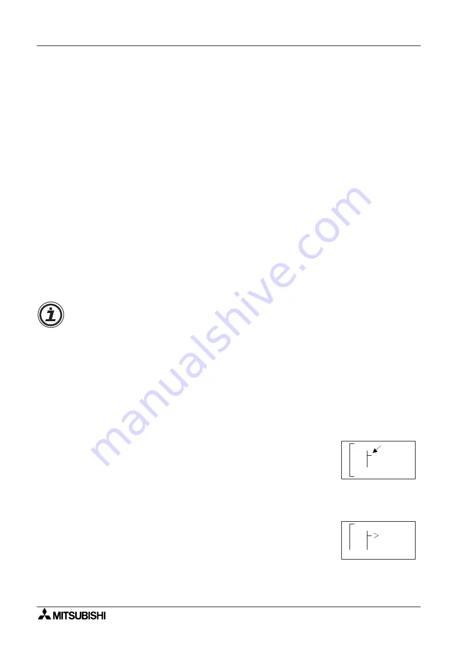
1 ) Step 1: Select the block providing the data to be output and move to the right until the
output pin is flashing. Press the “+” button to “add” a block.
2 ) Step 2: Choices will appear on the right side of the screen that include System Outputs (if
available), existing Function Blocks that have free input pins, and the option to add a new
function block (AddFB, see section 4.4). Scroll to the preferred option and select using the
“OK” key.
1
n
I
0
1
o
C
0
n
n
c
e t
d
A
F
d B
0
O 1


