α2
Simple Application Controllers
Direct Programming 4
4 - 2
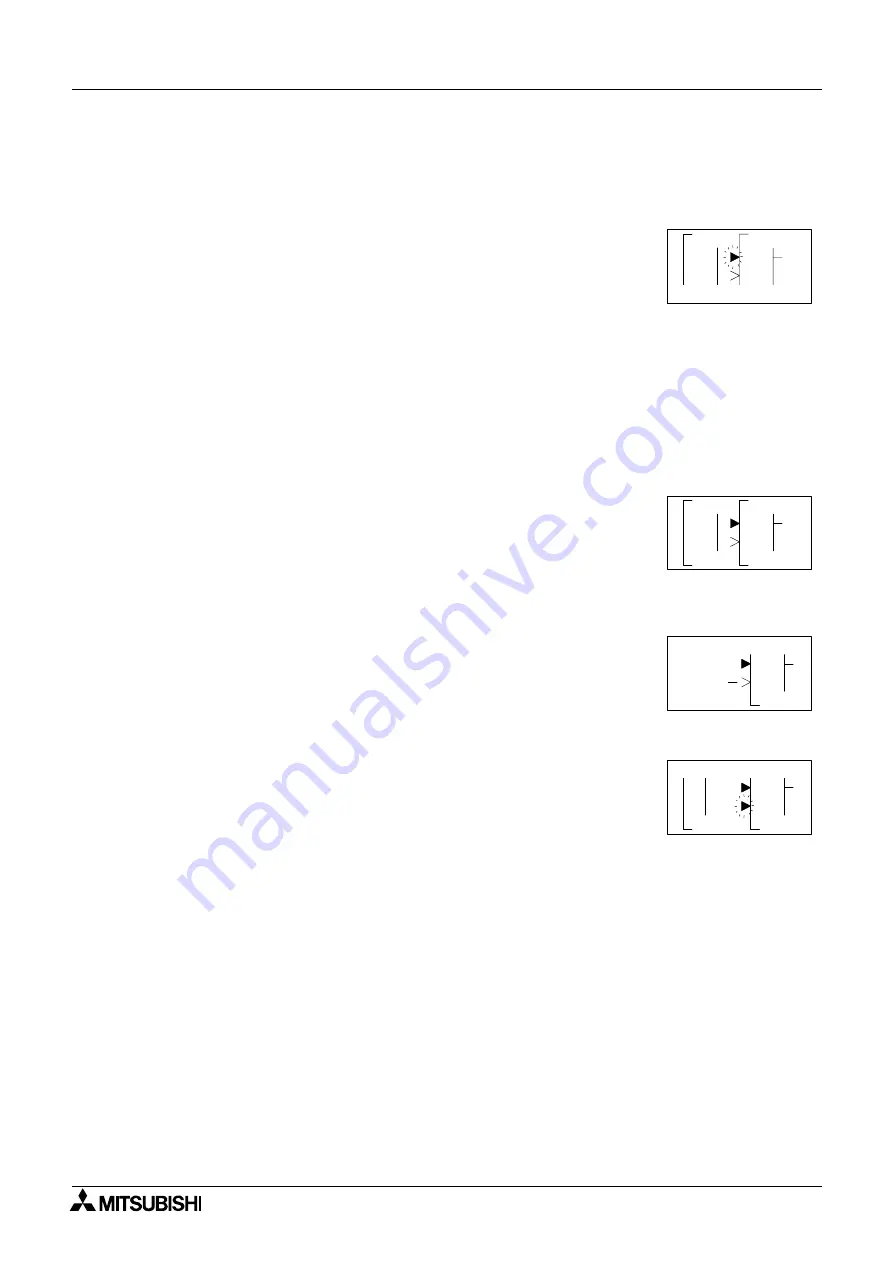
3 ) Step 3: The block accepting the signal will display as many of its input pins as possible (at
times they will not all fit on-screen). Pins that have been used will show as filled triangles;
pins that are open will show as “>” signs. A “Connect” prompt will appear on-screen, either
above or below the left hand block. The current input choice will flash. Scroll to the desired
pin and press the “OK” key to accept. The process is complete.
4.2.2
To connect the blocks from the right (signal receiver) block to left (signal
provider) block.
It is necessary to choose the block input pin (Step 1), the signal provider (Step 2), and to
accept the connection (Step 3).
1 ) Step 1: Select the block that will be receiving the signal and move left until an input pin is
flashing. Scroll to the desired unused input pin (“>”). Press the “+” key to begin the
connection process.
2 ) Step 2: Because output pins may have multiple connections, all the Keys, Function Blocks,
System Inputs, Outputs will show on the left of the screen as well as an option to “AddFB”.
Scroll to the preferred option and Press the “OK” key.
3 ) Step 3: The chosen connection will be flashing on-screen along with the “Connect” prompt.
Press the “OK” key to accept.
4.3
Disconnect Two Blocks
Blocks can be disconnected by implementing the following procedure.
Move to the connection that is to be disconnected. Enter “-” as the disconnect command. A
“Disconnect” prompt will appear on-screen. Press the “OK” key to accept the disconnect.
1
o
C
0
n
n
c
e t
0 1
0
P
1
0
n
I
0 1
0
P
N
C
n
n
0
M
P
N
C
o
C
t
c
F
d
d
A
B
e
1
n
n
n
I
P
N
C
o
C
t
c
e


