


-
64
-
'14 • SR-T-157
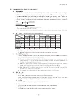
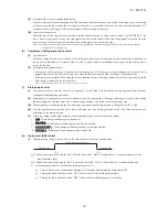
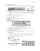
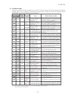
(p) Heating overload protection
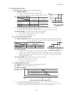
(i)
If the indoor heat exchanger temperature (detected with ThI-R) at 63°C or higher is detected for 2 seconds continuously,
the compressor stops. When the compressor is restarted after a 3-minute delay, if a temperature at 63°C or higher is
detected for 2 seconds continuously within 60 minutes after initial detection and if this is detected 5 times consecutively,
the compressor stops with the anomalous stop (E8). Anomalous stop occurs also when the indoor heat exchanger
temperature at 63°C or higher is detected for 6 minutes continuously.
56
63
Indoor heat exchanger temperature (°
C)
Compressor ON
Compressor OFF
(ii)
Indoor unit fan speed selection
If, after second detection of heating overload protection up to fourth, the indoor fan is set at Me and Lo taps when the
compressor is turned ON, the indoor fan speed is increased by 1 tap.
(q) Anomalous fan motor
(i)
After starting the fan motor, if the fan motor speed is 200min
-1
or less is detected for 30 seconds continuously and 4 times
within 60 minutes, then fan motor stops with the anomalous stop (E16).
(ii)
If the fan motor fails to reach at -50 rpm less than the required speed, it stops with the anomalous stop (E20).
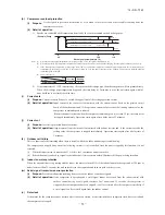
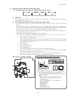
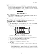
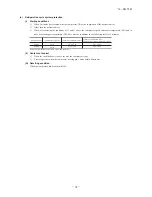
(r) Plural unit control – Control of 16 units group by one remote control
(i)
Function
One remote control switch can control a group of multiple number of unit (Max. 16 indoor units). “Operation mode”
which is set by the remote control switch can operate or stop all units in the group one after another in the order of unit
No.
(1)
. Thermostat and protective function of each unit function independently.
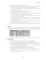
Note (1) Unit No. is set by SW2 on the indoor unit control PCB. Unit No. setting by SW2 is necessary for the indoor unit only.
SW2: For setting of 0 – 9, A – F
Remote control
Indoor unit
Outdoor unit
Signal wiring
between outdoor unit
and indoor units
(Master unit)
Remote control wiring
R
0
1
2
3
F
4
Refrigerant piping
(2) Unit No. may be set at random unless duplicated, it should be better to set orderly like 0, 1, 2…, F to avoid mistake.
(ii)
Display to the remote control
1) Center or each remote control basis, heating preparation: the youngest unit No. among the operating units in the
remote mode (or the center mode unless the remote mode is available) is displayed.
2) Inspection display, filter sign: Any of unit that starts initially is displayed.
3) Confirmation of connected units
Pressing “AIR CON No.” button on the remote control displays the indoor unit address. If “▲” “▼” button is
pressed at the next, it is displayed orderly starting from the unit of youngest No.
4) In case of anomaly
a) If any anomaly occurs on a unit in a group (a protective function operates), that unit stops with the anomalous
stop but any other normal units continue to run as they are.
b) Signal wiring procedure
Signal wiring between indoor and outdoor units should be made on each unit same as the normal wiring. For
the group control, lay connect with sires wiring between rooms using terminal blocks (X, Y) of remote control.
Connect the remote control communication wire separately from the power supply wire or wires of other
electric devices (AC220V or higher).