


-6-
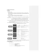
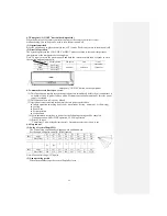
2.5 Performance curve
The cooling and heating capacities are measured in the following conditions. The actual capacity
can be obtained with the following formula.
Actual capacity = Rating capacity x Correction factor
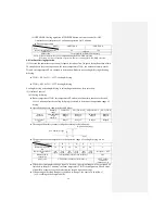
(1) Capacity correction according to indoor and outdoor temperatures:
Outdoor air W.B. temperature (°C W.B.) ISO-T1 Standard
⑵
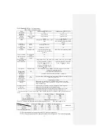
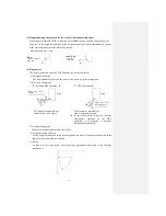
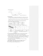
Capacity correction according to one way length of refrigerant piping:
It is necessary to correct the cooling and heating capacity according to the one way length of
refrigerant piping.
Piping length (m)
7
10
15
Cooling
1.0
0.99
0.975
Heating
1.0
1.0
1.0
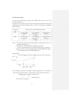
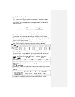
⑶
Capacity correction according to frosting on outdoor heat exchanger during heating:
In additions to the foregoing corrections (1) and (2), the heating capacity also needs to be
corrected according to the frosting on the outdoor heat exchanger.
Air inlet temperature of
outdoor unit
-10
-9
-7
-5
-3
-1
1
3
5
Frosting correction factor
0.95
0.94
0.93
0.91
0.88
0.86
0.87
0.92
1.00
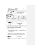
⑷
Example of cooling and heating capacity calculation:
The actual cooling capacity of model SRK25QA-S with the one way piping length of 25m at the
indoor wet-bulb temperature of 19
℃
and outdoor dry-bulb temperature of 35
℃
in summer or
indoor dry-bulb temperature of 20
℃
, outdoor dry-bulb temperature of 1
℃
and indoor wet-bulb
temperature of -1
℃
in winter is
Actual cooling capacity = 2500 x 1.0 x 0.95 ≈ 2375W
Nominal cooling Temp. correction Piping length
capacity factor correction factor
Actual heating capacity = 3200 x 0.81 x 0.95 x 0.86 ≈ 2118W
Nominal heating Temp. correction Piping length Frosting
capacity factor correction factor correction factor
Cooling
Heating
Accommodation
C
o
o
li
n
g
o
p
er
at
io
n
H
ea
ti
n
g
o
p
erat
io
n
In
d
o
o
r
ai
r
D
.B.
te
mp
erat
u
re
O
u
td
o
o
r
ai
r
D
.B.
te
mp
erat
u
re
Indoor air W.B. temperature (°C W.B.) ISO-T1 Standard
Co
rre
ct
io
n
fact
o
r
o
f
co
o
li
n
g
&
h
ea
ti
n
g
cap
aci
ty
i
n
r
el
at
io
n
t
o
t
emp
era
tu
re
Summary of Contents for SRC25QA-S
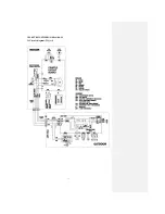
Page 10: ... 7 3 ELECTRICAL WIRING DIAGRAM 3 1 Circuit diagram 25QA S ...
Page 11: ... 8 3 2 Circuit diagram 35QA S ...
Page 22: ... 19 B Prevent Range I in jiggle operation from changing to Range C operation ...
Page 58: ... 55 12 Check method for outdoor unit 1 Circuit diagram of 25QA S outdoor unit ...
Page 59: ... 56 2 Circuit diagram of 35QA S outdoor unit ...
Page 81: ... 78 ...
Page 86: ... 83 RAC SRK35QA S PANEL FAN ASSY ...
Page 88: ... 85 20 21 RYD436A021 LOUVER ASSY 1 20 RYD436A020 LOUVER 12 21 RYD129A048 PLATE CONNECTING 2 ...
Page 92: ... 89 ...
Page 94: ... 91 ...
Page 98: ... ...
Page 100: ... 19 RYF937A002A CLAMP WIRE 1 ...