


-72-
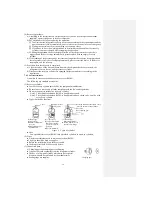
f) After charging the liquid refrigerant into the air conditioner by closing the charging valve,
fully close Valve
Lo
of the manifold pressure gauge to stop.
②⑤
g) Quickly move the charge hose away from the service opening.
⑥
If the movement is slow, the circulating refrigerant may be leaked.
h) Secure the covers of the service opening and control valve, and check for any gas leakage
around the covers.
⑥⑦
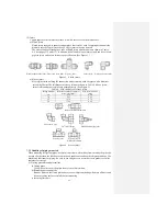
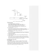
Figure 7 Structure for additional refrigerant charging
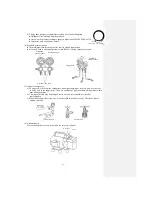
7.3.3 Removal (when new refrigerant piping is used)
(1) Removing the equipment
a) To recover
refrigerant from the outdoor unit through evacuation
● Use the manifold pressure gauge for R410A in evacuation.
● Recover
refrigerant from the outdoor unit when the equipment is operating in the HI
POWER
cooling mode.
(For the steps and precautions for recovery, see the user’s manual prepared by the
equipment manufacturer.)
* Precaution:
Use the refrigerant recovery device for outdoor unit in which evacuation is impossible.
b) To remove indoor unit/ outdoor unit
●Remove the pipes and wires between the indoor and outdoor units.
●Tighten the control valve and service opening of the outdoor unit to the specified torque.
●Tighten the flare nut with cap at the connection between the indoor and outdoor units to
the specified torque.
● Remove the indoor unit/outdoor unit.
* Precaution:
Be careful not to break the piping for the indoor unit when it is stored in the original
place.
(2) Installing the equipment
a) According to the steps described in “7.3.2 New installation”.
7.3.4 Replacing equipment (never use the existing refrigerant piping)
To replace an air conditioner using conventional refrigerant (R22) with one using the alternative
refrigerant (R410A) or replace an air conditioner using the alternative refrigerant (R410A) with
another using the alternative refrigerant (R410A), please use completely new refrigerant piping
(1), otherwise the difference of pressure properties of refrigerants or the difference of lubricants
may cause failure. (Not all air conditioners using R410A use the same type of lubricant.)
7.3.5 Refitting equipment
Do not charge the air conditioner which used the conventional refrigerant (R22) with the
alternative refrigerant (R410A). Otherwise, the equipment may malfunction or such severe
consequences as interruption of refrigerant cycle, etc.
(Liquid side)
(Indoor unit)
(Outdoor unit)
Control valve
⑦
(2-way)
Start
(Gas side)
Control valve
⑦
(3-way)
Start
Service opening
⑥
Charging valve
②
Service opening
④
Refrigerant cylinder
(with syphon tube)
Electronic loadcell scale for charging refrigerant
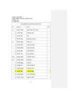
Summary of Contents for SRC25QA-S
Page 10: ... 7 3 ELECTRICAL WIRING DIAGRAM 3 1 Circuit diagram 25QA S ...
Page 11: ... 8 3 2 Circuit diagram 35QA S ...
Page 22: ... 19 B Prevent Range I in jiggle operation from changing to Range C operation ...
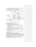
Page 58: ... 55 12 Check method for outdoor unit 1 Circuit diagram of 25QA S outdoor unit ...
Page 59: ... 56 2 Circuit diagram of 35QA S outdoor unit ...
Page 81: ... 78 ...
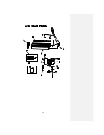
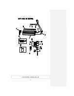
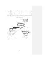
Page 86: ... 83 RAC SRK35QA S PANEL FAN ASSY ...
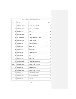
Page 88: ... 85 20 21 RYD436A021 LOUVER ASSY 1 20 RYD436A020 LOUVER 12 21 RYD129A048 PLATE CONNECTING 2 ...
Page 92: ... 89 ...
Page 94: ... 91 ...
Page 98: ... ...
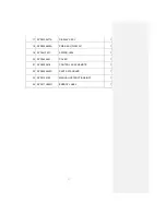
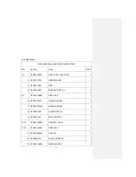
Page 100: ... 19 RYF937A002A CLAMP WIRE 1 ...