


-44-
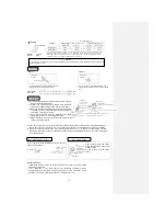
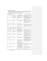
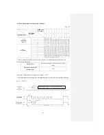
Notes: (1) The number of flashes in service mode excludes the 1.5 sec. light-up (beginning signal).
(See the following example.)
● Safe current (heating safety I) (for example, the stop code is “32”)
RUN lamp (tens place) flashes 3 times and TIMER lamp (ones place) flashes 2
times:
3 x 10 + 2 x 1 = 32. The code 32 “Safe current (heating safety I)” can be read from
the list.
(2) Abnormal stop indication: - No indication (automatic restoration only)
O With indication
Indication with ( ) means the number of automatic
restorations for the same cause, with error indication.
Indication without ( ) means one error indication occurs.
(3) Automatic restoration: - No indication
O With indication
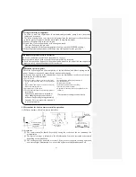
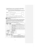
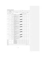
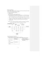
(d) Remote controller information list
1) Operation switching 2) Air flow switching
Indication in service
mode
Operation switching
status at the time of
abnormal stop
Indication in service
mode
Air flow switching status
at the time of abnormal
stop
RUN lamp
(Operation switching)
TIMER lamp
(Air flow switching)
0
AUTO
0
AUTO
1
DRYING
2
HI
2
COOLING
3
ME
4
HEATING
4
LO
6
HI POWER
7
ECONO
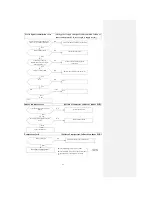
* If there is no data recorded (the error code is normal), the information on the remote controller is
as showed in the table below:
Settings of remote controller
Indication when the error code is normal
Operation switching
AUTO
Air flow switching
AUTO
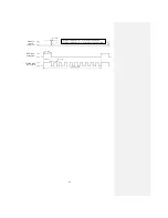
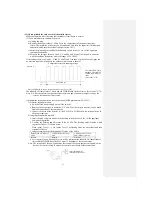
(Example): Operation switching: Cooling, Air flow switching: HI
RUN lamp
(tens place)
TIMER lamp
(ones place)
1.5 sec.
0.5 sec.
0.5 sec.
11 sec. cycle
RUN lamp
(tens place)
TIMER lamp
(ones place)
1.5 sec.
0.5 sec.
0.5 sec.
11 sec. cycle
Summary of Contents for SRC25QA-S
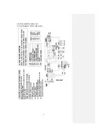
Page 10: ... 7 3 ELECTRICAL WIRING DIAGRAM 3 1 Circuit diagram 25QA S ...
Page 11: ... 8 3 2 Circuit diagram 35QA S ...
Page 22: ... 19 B Prevent Range I in jiggle operation from changing to Range C operation ...
Page 58: ... 55 12 Check method for outdoor unit 1 Circuit diagram of 25QA S outdoor unit ...
Page 59: ... 56 2 Circuit diagram of 35QA S outdoor unit ...
Page 81: ... 78 ...
Page 86: ... 83 RAC SRK35QA S PANEL FAN ASSY ...
Page 88: ... 85 20 21 RYD436A021 LOUVER ASSY 1 20 RYD436A020 LOUVER 12 21 RYD129A048 PLATE CONNECTING 2 ...
Page 92: ... 89 ...
Page 94: ... 91 ...
Page 98: ... ...
Page 100: ... 19 RYF937A002A CLAMP WIRE 1 ...