


-59-
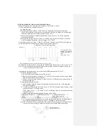
2) 35QA-S uses DC motor.
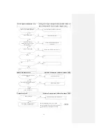
● Failure diagnosis method for outdoor circuit board or motor when the fan motor can’t operate
● Check it after confirming the indoor unit is normal.
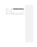
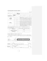
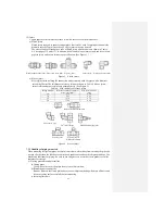
(1) Output check of outdoor circuit board
1) Unplug the plug.
2) Remove the plug CAN for the outdoor fan motor.
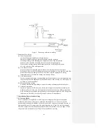
3) Insert the plug and press and hold the back-up switch for over 5 sec. (ON) till the indoor
unit commences operation. If, 20 sec. after the back-up switch is turned ON, the contact
pin No.
②
of the plug as shown in the following figure outputs voltage for about 30 sec.,
it indicates the circuit board is basically normal and the fan motor malfunctions. If there is
no voltage output, it indicates the circuit board malfunctions and the fan motor is
basically normal.
Note (1) After the one-time output another 30 seconds after the contact pin
②
of the plug
outputs voltage for 3 minutes, the error of the indoor unit is detected.
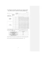
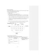
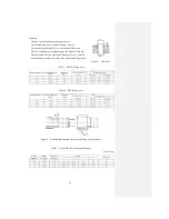
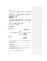
(ii) Checking resistance of DC fan motor
Measure the resistance between the terminals with a multimeter.
Measurement point
Resistance value in
normal cases
Notes: (1) Remove the fan motor and
measure without power.
(2) The fan motor is abnormal if the
measurement is below the
normal value.
①
-
③
(red and
black)
Above 25MΩ
④
-
③
(white and
black)
Above 30MΩ
Red Black White Yellow Blue
DC several V
Circuit board of
outdoor unit
Summary of Contents for SRC25QA-S
Page 10: ... 7 3 ELECTRICAL WIRING DIAGRAM 3 1 Circuit diagram 25QA S ...
Page 11: ... 8 3 2 Circuit diagram 35QA S ...
Page 22: ... 19 B Prevent Range I in jiggle operation from changing to Range C operation ...
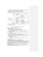
Page 58: ... 55 12 Check method for outdoor unit 1 Circuit diagram of 25QA S outdoor unit ...
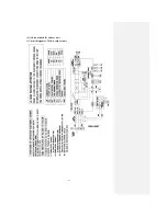
Page 59: ... 56 2 Circuit diagram of 35QA S outdoor unit ...
Page 81: ... 78 ...
Page 86: ... 83 RAC SRK35QA S PANEL FAN ASSY ...
Page 88: ... 85 20 21 RYD436A021 LOUVER ASSY 1 20 RYD436A020 LOUVER 12 21 RYD129A048 PLATE CONNECTING 2 ...
Page 92: ... 89 ...
Page 94: ... 91 ...
Page 98: ... ...
Page 100: ... 19 RYF937A002A CLAMP WIRE 1 ...