background image

8-11

Chapter 8 PERIODIC INSPECTION AND MAINTENANCE PROCEDURES

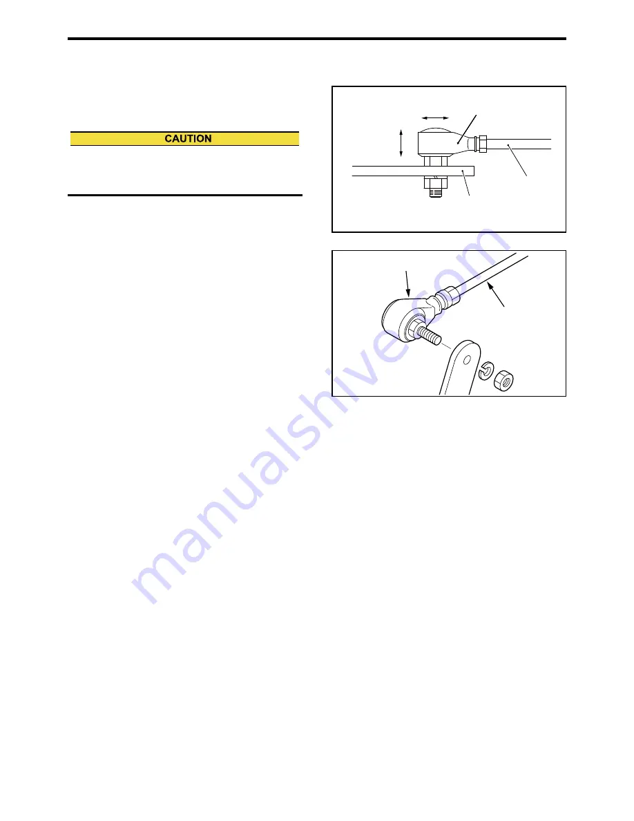
Fuel Control Link Ball Joint - Inspect

Check ball joint in the fuel control link for play. If the 
amount of play is 0.1 mm [0.004 in.] or more, replace 
the ball joint with the new one. 

If the ball joints are integrated in the control link, 
replace the control link when the ball joints have loos-
ened. When installing ball joints, be sure to tighten the 
nuts firmly. 

Fig. 8-12 Ball Joints For Looseness - Inspect

Fig. 8-13 Fuel Control Link - Remove

If the sealed ball joints are found loosened, contact a 
dealer of Mitsubishi Heavy Industries, Ltd. If the seal 
on the ball joint is broken, the warranty is invalidated. 

Ball joint

Rod

Lever

0.1 mm

[0.004 in.]

0.1 mm

[0.004 in.]

Ball joint

Control link

Summary of Contents for SA

Page 1: ...requested to read this Oper ation and Maintenance Manual carefully before operating the engine or conducting inspection and maintenance Never operate the engine or conduct maintenance work with out completely understanding this manual OPERATION MAINTENANCE MANUAL 1 ...

Page 2: ...ontents which are overlapping between the chapters Please read this manual thoroughly before proceeding with operation inspection and maintenance work for correct use and servicing Failure to follow directions in this manual may result in serious accidents Please observe the contents of the controls which are applied in the countries or areas when using the engines from Mitsubishi Heavy Industries...

Page 3: ...or use or against infringement of any patent Mitsubishi Heavy Industries Ltd will not be liable for any damages or consequential damages including but not limited to damages or other costs resulting from any abuse misuse misapplication of the engine and devices supplied from us Mitsubishi Heavy Industries Ltd will not be liable for any damages or personal injuries resulting from any modification w...

Page 4: ... these regulations within the warranty period Warranty Period Then its warranty period is 5 years or 3000 hours whichever comes first However if your engine warranty period is longer than the emission warranty period the emission warranty period extends to same as the engine warranty period Below warranty period shall begin on the date the engine is delivered to the first owner Warranted Parts Mit...

Page 5: ...r you are responsible for the performance of the required maintenance listed in your owner s manual Mitsubishi Heavy Industries Ltd recommends that you retain all receipts covering maintenance on your heavy duty off road engine but Mitsubishi Heavy Industries Ltd never deny warranty solely for the lack of receipts or for your failure to ensure the performance of all scheduled maintenance As the he...

Page 6: ...A statement in such writ ten instructions to the effect of repair or replace as necessary shall not reduce the period of warranty coverage Any such part repaired or replaced under the warranty shall be warranted for the remaining war ranty period 3 Any warranted part which is scheduled for replacement as required maintenance in the written instructions required in Subsection e shall be warranted f...

Page 7: ... hot air intake system B Intake manifold C Heat riser valve and assembly D Turbocharger supercharger systems E Charged air cooling systems 3 Exhaust gas recirculation EGR system A EGR valve body and carburetor spacer if applicable B EGR rate feedback and control system 4 Air injection system A Air pump or pulse valve B Valves affecting distribution of flow C Distribution manifold 5 Catalyst or the...

Page 8: ...s or devices and mount ing hardware D Pulleys belts and idlers E Emission control information labels F Any other part with the primary purpose of reducing emissions or that can increase emission during fail ure without significantly degrading engine performance e Mitsubishi Heavy Industries Ltd shall furnish with each new engine written instructions for the maintenance and use of the engine by the...

Page 9: ...t be operated maintained and inspected only by qualified persons who have thor ough knowledge of engines and their dangers and who also have received risk avoidance training To prevent an accident do not attempt to carry out any operation other than those described in this man ual and do not use the engine for any unapproved purpose When the ownership of the engine is transferred be sure to provid...

Page 10: ...ctions could lead to serious accidents which could result in personal injury or death in the worst case Understand the directions well and handle engines with following directions Indicates an immediately hazardous situation which if not avoided will result in death or serious injury Indicates a potentially hazardous situation which if not avoided could result in death or serious injury Indicates ...

Page 11: ... kW 1 341 HP 1 3596 PS Meter of mercury 1 kPa 0 75 cmHg Meter of water 1 kPa 10 197 cmH2O cmAq Rotation speed 1 min 1 1 rpm Kinetic viscosity 1 mm2 s 1 cSt ABBREVIATIONS STANDARD AND OTHERS API American Petroleum Institute ASTM American Society for Testing and Materials ISO International Organization for Standardization JIS Japanese Industrial Standards LLC Long Life Coolant MIL Military Specifica...

Page 12: ...pening and Closing Radiator Cap 1 4 Do Not Touch High Pressure Injection Fuel 1 4 Be Careful When Handling Fuel Engine Oil or LLC 1 5 Use Only Specified Fuel Engine Oil and LLC 1 5 Handle LLC Carefully 1 5 Proper Disposal of Waste Oil LLC and Coolant 1 5 When Abnormality Occurs 1 5 Do Not Add Coolant Immediately After a Sudden Stop Due to Overheating 1 5 Stop Operation Immediately If You Notice An...

Page 13: ...3 Cautions During Operation 3 13 Inspection During Operation 3 13 Stop 3 14 Emergency Stop 3 14 Inspection After Stopping 3 14 Chapter 4 FUEL Recommended Fuel 4 1 Handling Fuel 4 1 Fuel Specification 4 2 Chapter 5 ENGINE OIL Recommended Engine Oil 5 1 Engine Oil Grade 5 1 Engine Oil Specification 5 2 Selection of Oil Viscosity 5 3 Handling Engine Oil 5 3 Service Limits of Engine Oil 5 4 Definition...

Page 14: ...aner Check for Clogging 8 21 Air Cleaner Element Clean Check and Replace 8 22 Electrical System 8 24 Starter Inspect 8 25 Alternator Inspect 8 25 Air Starter System 8 26 Air Strainer Drain Water and Clean 8 26 Air Tank Drain Water 8 26 Air Tank Inspect Safety Valve Operation 8 27 Chapter 9 LONG TERM STORAGE Storing the Engine in an Inoperable Condition for 3 Months or More 9 1 Preparation for Stor...

Page 15: ...or Clogging 3 10 Fig 3 17 Air Tank Drain Water 3 10 Fig 3 18 Starting Air Tank Air Pressure Check 3 11 Fig 3 19 Thermo label of damper 3 11 Fig 3 20 Manual Stop Lever 3 14 Fig 5 1 Engine Oil Grade 5 1 Fig 5 2 Selection of Oil Viscosity 5 3 Fig 6 1 GLASSY LLC 6 1 Fig 8 1 Adjusting the Belt Tension 8 2 Fig 8 2 Damper Check Visually 8 4 Fig 8 3 Damper Temperature Management 8 5 Fig 8 4 Fuel Tank Drai...

Page 16: ...Table 6 2 LLC Specification 6 3 Table 6 3 Recommended LLC Concentration 6 6 Table 7 1 Periodic Maintenance Chart for Regular Use Engine 7 3 Table 7 2 Periodic Maintenance Chart for Emergency Engine 7 5 Table 7 3 Periodic Maintenance Chart for General Purpose Engine 7 9 Table 8 1 Ribbed Belt Tension Force 8 3 Table 8 2 Damper Temperature Management 8 4 Table 8 3 Thermo Label for Temperature Managem...

Page 17: ... Cover Until Engine Cools Do not attempt to open the side cover of the crank case before the engine cools down Wait at least 10 minutes after stopping the engine Opening the cover when the engine is hot allows fresh air to flow into the crankcase which can cause oil mist to ignite and explode Care for Fuel Oil and Exhaust Gas Leakage If any fuel oil or exhaust gas leaks are found immedi ately stop...

Page 18: ...he clothing or outfitting is caught by a rotating part serious bodily injuries could result Lockout and Tagout Be sure to lockout and tagout before starting inspec tion and maintenance Lockout and tagout are effective methods of cutting off machines and equipment from energy sources To accomplish the lockout tagout remove the starter switch key set the battery switch to OFF and attach a Do Not Run...

Page 19: ...nly When mounting generator on the engine use the special hanger of common bed Hangers of engine cannot be used When mounting marine gear on the engine be sure not to apply the load on the hangers of engine only Keep the angle formed by slings attached to hangers within 60 If the angle exceeds this limit excessive load could be imposed on the hangers and this could damage the hangers and result in...

Page 20: ...ields If any of these heat shields have been removed owing to unavoidable circumstances during the work be sure to restore them after the work is completed Be Careful of Opening and Closing Radiator Cap Never open the radiator cap while the engine is run ning or immediately after the engine is stopped To open the cap stop the engine and allow the coolant temperature to lower sufficiently To open t...

Page 21: ...bnormality Occurs Do Not Add Coolant Immedi ately After a Sudden Stop Due to Overheating If the engine stops suddenly or if you have no choice but stop the engine suddenly due to overheating do not add coolant immediately Adding water while the engine is hot can damage parts such as cylinder heads due to a sudden drop of temperature Add coolant gradually after the engine has completely cooled Stop...

Page 22: ...p can cause sparks that may result in an explosion Before servicing electrical components or conducting electric welding set the battery switch to Open OFF position or remove the plug from the negative ter minal to cut off the electrical current Battery electrolyte contains dilute sulfuric acid Care less handling of the battery can cause the loss of sight and or skin burns Also do not swallow the ...

Page 23: ...er balance between fuel injection volume and governor operation or overrunning of the engine which could re sult in a serious accident Perform All Specified Pre oper ation Inspections and Periodic Inspections Conduct the pre operation inspections and periodic inspections as described in this manual Failure to conduct the specified inspections may cause various engine problems damage to parts and s...

Page 24: ...e following instructions Never service the air cleaner while the engine is run ning The turbocharger may suck particles of foreign materials into the engine and could result in serious accidents Remove the air cleaner slowly to prevent foreign ma terials accumulated on the element from falling off Af ter removing the air cleaner immediately cover the air inlet with plastic sheet or similar means t...

Page 25: ...aution labels use a cloth water and soap Do not use cleaning solvents gasoline or other chemicals to prevent the letters from getting blurred or the adhesion from being weakened Replace damaged or fractured labels with new ones If any engine part on which a warning label is attached is replaced with a new one attach a new identical warning label to the new part To obtain new warning labels contact...

Page 26: ...eather Fuel filter Oil level gauge Oil pan Fuel filter Wire element type㸧 Governor Governor oil filter Starter Fuel injection pump Fuel feed pump Air cooler Turbocharger Rear Front Name plate Fuel inlet Fuel return port Stop solenoid Rear Front Air cooler Starter Oil filter Bypass oil filter Oil cooler Thermostat Coolant outlet Fuel injection pump Fuel feed pump Fuel filter Exhaust outlet Air inta...

Page 27: ...is located in the fuel control link is moved in the STOP direction the engine stops If the engine continues to operate even after the man ual stop lever is moved in the STOP direction cut off the fuel supply to stop the engine Fig 2 4 Manual Stop Lever Stop Solenoid The stop solenoid operates for normal shutdown of engine operation The stop solenoid moves the rack of fuel injection pump to cut the...

Page 28: ...fully and understand functions of each device Oil Pressure Unit Indicate the oil pressure Fig 2 6 Oil Pressure Unit Thermo Unit Always detect the coolant temperature of engine Fig 2 7 Thermo Unit Revolution Detection Pickup It is installed in the timing gear case and always detect engine speed Fig 2 8 Revolution Detection Pickup Oil pressure unit Thermo unit ...

Page 29: ...alues and shapes vary depending on the engine specifications Oil Pressure Switch The oil pressure switch generates an alarm when the engine oil pressure becomes low and reaches the specified pressure Fig 2 9 Oil Pressure Switch Thermo Switch The oil pressure switch generates an alarm when the engine coolant temperature becomes high and reaches the specified temperature Fig 2 10 Thermo Switch Oil F...

Page 30: ...ner Indicator If the element is clogged the intake air is decreased and the red signal mark will be displayed The signal indicates only and does not generate an alarm Therefore the periodic visually inspection is needed Press the reset button on the top of air cleaner indica tor and restore the signal after cleaned the air cleaner indicator or replaced with a new one Fig 2 13 Air Cleaner Indicator...

Page 31: ...uel 7 Refill fuel tank until fuel level gauge indicates FULL level line after checking the contact of float switch Check that the following contents are performed before the engine is operated Failure to do so may cause various problems and will shorten the service life of the engine Prevent from spreading water especially seawater or rainwater and entering foreign materials to the air inlet openi...

Page 32: ... the air vent plug of the fuel filter about 1 5 turns 2 Move the priming pump up and down then feed fu el 3 When the fuel from the air vent plug becomes free from air bubbles stop priming and tighten the air vent plug to the specified torque Fig 3 3 Fuel Filter Bleed Air When fuel overflow from the air vent plug wipe thor oughly Spilled fuel causes fire hazard After bleeding lock the priming pump ...

Page 33: ...ck the mounting position of head packing Note If the head packing has abnormality such as de formation or scratches consult a dealer of Mit subishi Heavy Industries Ltd as the priming pump needs to be changed Fig 3 5 Priming Pump Tightening Method Fig 3 6 Priming Pump Head Packing Air vent plug Priming pump Fuel injection pumps are located on the both banks of engine Never fail to tighten the prim...

Page 34: ... If the engine oil is low refill the specified engine oil 9 Check the oil pan and other area for oil leaks Re pair the oil leakage if any 10 While pulling the stop lever rotate the crankshaft for approx 10 seconds to turn on the starter Stop the operation for 1 minute then repeat the opera tion two or three times Circulate engine oil to each engine parts Note Prepare for the cooling system 11 Star...

Page 35: ...lant reaches the full level close the cool ant filler securely 5 While pulling the manual stop lever rotate the crankshaft for approx 10 seconds using the start er Stop the operation for approx 1 minute then re peat the operation two or three times to bleed the cooling system Note Prepare for the engine oil system 6 Check the level of coolant Fig 3 10 Coolant Drain Cock Engine Fig 3 11 Coolant Dra...

Page 36: ...ce level is about 10 to 15 mm 0 39 to 0 59 in above the top of the plates If the electrolyte level is low remove the caps and add distilled water to the proper level Note When adding distilled water add little by little Fig 3 12 Battery Electrolyte Level Inspect If battery electrolyte is spilled on your skin or clothes flush immediately with plenty of water If battery electrolyte get into your eye...

Page 37: ...uel engine oil or coolant 3 At 30 minutes after the engine stop check the oil level with the oil level gauge The proper oil level is between the high and low marks on the oil level gauge 4 If the engine oil goes over the high marks on the oil level gauge open the engine oil drain valve to drain oil If the engine oil is low refill the specified engine oil 5 Open the coolant filler cap and check the...

Page 38: ...ndustries Ltd 3 Visually check bolts and nuts for looseness 4 Check the electrical wiring including the starters and alternator 5 Check that valves plugs or cocks are properly po sitioned Fuel feed valve Open Coolant drain cock plug Closed Engine oil drain plug Closed Air supply valve air tank Open Fig 3 13 Valves for open closed position Check Should an engine abnormality be observed during opera...

Page 39: ... The proper oil level is between the high and low marks on the oil level gauge If the engine oil goes over the high marks on the oil level gauge open the engine oil drain valve to drain oil If the engine oil is low refill the specified engine oil 4 Install the oil filler cap after adding engine oil 5 Check the oil pan and other area for oil leaks Fig 3 15 Oil Filler and Oil Level Gauge When workin...

Page 40: ... cleaner differs from the contents of this operation manual follow the manufacturer s operation manual Fig 3 16 Air Cleaner Check for Clogging Air Tank Drain Water 1 Open the drain valve slowly and check that water in the tank is drained from drain pipe 2 After water is drained and the air is discharged in the tank tighten the drain valve firmly 3 Loosen the drain handle on the bottom of drain sep...

Page 41: ...It is recommended to use the thermo label for temper ature management of the damper Check the thermo label before starting engine 1 Check the thermal part of thermo label is black 2 Note the highest temperature of thermal part Note the temperature periodically and check the abnor mality of temperature alteration Note For damper temperature limit and inspection re fer to Damper Inspect 8 4 Fig 3 19...

Page 42: ...ection During Warm up During warm up operation walk around the engine and check for fuel oil coolant or exhaust gas leaks Before starting the engine check to make sure no one is near the engine and that tools are not left on or near the engine In a loud voice notify people in the area when starting the engine Do not apply a load to the engine at starting Disengage the clutch if equipped Continuous...

Page 43: ...perate the engine under a light load for break in operation Operating the new engine under heavy load or severe conditions during the break in period can shorten the service life of the engine Do not turn the battery switch OFF when the engine is running Turning off the battery switch during oper ation not only stops the instrument operations but also may deteriorate the alternator diode and regul...

Page 44: ... while engine parts are hot due to high speed operation can be a cause for heat up of the engine parts and shorten the engine life Before stopping the engine run the engine with the idle speed at low Rpms for 5 or 6 minutes to cool the engine and check the engine for abnormalities Never accelerate the engine immediately before shutting it down Do not restart the engine immediately after abnormal s...

Page 45: ...ing with fuel in the tank and also gives time for dust and water to separate and settle at the bottom of the tank Before refilling clean the areas around the caps thoroughly and remove the caps from the drum and tank Also clean your hands and the hose before refueling When using a hand operated pump be careful not to pump water or sediment accumulated at the bottom of the storage tank Be sure to u...

Page 46: ...x new type 45 or higher JISK2280 1996 ISO DIS 4264 Kinetic viscosity 2 0 mm2 s 0 0031 in2 s or more at 30 C 86 F 8 0 mm2 s 0 0124 in2 s or more at 30 C 86 F JIS K 2283 2000 ISO 3104 Sulfur content 0 2 weight or lower 1 0 weight or lower Shorten lub oil change intervals JIS K 2541 2000 The content should be as low as the die sel fuel ISO 4260 ISO 8754 Water content and sediment 0 1 volume or lower ...

Page 47: ...at WS 1 4 kPa 0 0143 kgf cm2 0 2031 psi ISO 12156 1 BDF Biodiesel fuel FAME Fatty Acid Methyl Ester BDF quality shall meet JIS K 2390 or ASTM D 6751 or EN14214 BDF blending of 5 by volume or less is approved JIS K 2390 2008 FAME for mixing ASTM D 6751 EN 14214 Engine applications for regular prime use Regular for emergency use Emergency Selection according to application Table 4 2 Recommended Limi...

Page 48: ... sification CF or CH 4 When using the CF class engine oil it must be certi fied according to API service classification CF by 2009 and satisfied the following Table 5 1 Table of Recom mended Limit of Engine Oil Properties When using the CH 4 class engine oil the sulfur con tent of fuel must be 0 2 weight or lower Fig 5 1 Engine Oil Grade Use the engine oils recommended in this manual only Never us...

Page 49: ...K 2265 ISO 3679 ISO 2719 ISO 2592 Base number Hydrochloric acid method Sulfur contents of fuel 1 0 weight or lower mgKOH g 10 or higher up to 13 JIS K 2501 ISO 3771 ISO 6618 ISO 6619 ISO 7537 0 2 weight or lower 8 or higher up to 13 Perchloric acid method Sulfur contents of fuel 1 0 weight or lower mgKOH g 13 or higher up to 16 0 2 weight or lower 11 or higher up to 16 Acid number mgKOH g 1 5 to 2...

Page 50: ...the legally specified quantities be sure to have the work per formed by a service station operated under the provision of the law When removing oil from the engine or oil can use an oil pump Do not suck oil using you mouth and a pipe Be sure to close the cap on the oil can after use Keep oil in a well ventilated place and out of direct sunlight Be sure to obtain the MSDS of the engine oil and foll...

Page 51: ...th new oil Table 5 2 Table of engine oil properties Properties Standard Test method Kinetic Viscosity mm2 s in2 s 100 C 212 F 30 or less rate of change from new oil 10 mm2 s 0 155 in2 s or more JIS K 2283 2007 ISO 3107 ISO 2909 30 or less rate of change from new oil 20 or less rate of change from new oil Base number mgKOH g 2 0 or more with hydrochloric acid HCL method 1 2 of new oil or more with ...

Page 52: ...oxidation or sulfurous acid or sulfuric acid derived by the combustion of sul fur content of fuel or the oil becomes contaminated with imperfect combustion products An increase in the acid number will result in corrosion or wear of the inner parts of the engine such as cylin der liners or metal due to sulfur content and piston ring seizure due to sludge Water Content Water in oil promotes corrosio...

Page 53: ...oil due to abrasion by which worn parts can be located Water LLC or salt that should not be in engine oil can be detected Engine oil deteriorating conditions by which appropriate engine oil renewal intervals operating conditions proper inspection and maintenance schedule can be planned The engine oil analysis service can diagnose the internal condition of the engine which is necessary when disas s...

Page 54: ...ification Genuine LLC Mitsubishi Heavy Industries Ltd recommends the use of our genuine long life coolant GLASSY long life coolant Ethylene glycol type and Eco friendly prod uct PG GLASSY long life coolant propylene glycol type which are most appropriate coolant for Mitsubi shi diesel engines Be sure to use our Genuine LLC Fig 6 1 GLASSY LLC Table 6 1 Water Quality Standards Item Chemical symbol U...

Page 55: ...ning malfunctions caused by the use of LLC that does not meet the following specifica tion General Demands of LLC LLC must be a homogeneous liquid without sedi ment When the LLC is diluted to 30 to 60 density the LLC shall not cause troubles such as corrosion and precip itation deposits in the engine cooling system LLC shall be mixed with other LLC that satisfies this specification and shall not s...

Page 56: ...g character ASTM D3306 01 30 vol 4 0 ml or less 331 3 vol 150 ml 0 032 gal or less Disappearance of bubble within 5 seconds Hard water adaptability 1 0 or less 50 vol Metallic causticity 88 2 C 190 4 35 6 F 336 2 Hr 30 vol E G 50 vol P G Metalspecimen Mass change Aluminum 0 30 mg cm2 Cast iron 0 15 mg cm2 Steel 0 15 mg cm2 Brass 0 15 mg cm2 Solder 0 30 mg cm2 Copper 0 15 mg cm2 Appearance of the s...

Page 57: ...0 mg cm2 Copper 0 30 mg cm2 Appearance of the specimen after testing No visible signs of corrosion on the surface excluding the area contacting to spacer However discoloration is acceptable Properties of liquid after the test pH 6 5 to 11 0 pH change Maximum 1 0 Appearance of liquid No remarkable discoloration separation and gel generation Condition of parts Pump seal Free from any malfunction liq...

Page 58: ...6 5 Chapter 6 COOLANT Storage stability vol 30 vol room temperature 6 Hr 0 3 or less Table 6 2 LLC Specification Property Standard ...

Page 59: ...g life coolant Ethylene glycol type or PG GLASSY long life coolant Non amine type For determining the accurate LLC concentration refer to the instructions for the LLC used Should coolant or LLC be accidentally swallowed induce vomiting immediately and seek medical attention If LLC should enter eyes flush immediately with plenty of water and seek medical attention LLC is toxic Never dispose of cool...

Page 60: ...osion than when plain soft water is used This is a typical problem caused by the use of inap propriate LLC Examples of Abnormali ties Caused by LLC Amine Type Pitting of Iron Parts Amines are generally effective in suppressing the rust ing of ferrous metals but they are said to cause prob lems for copper parts Dissolved copper copper corrosion in the cooling system deposits on iron parts and the c...

Page 61: ... following 3 categories Periodic Maintenance Chart for Regular Use Engine When the engine is used as a regular use engine perform the periodic inspection and maintenance in accordance with the Periodic Maintenance Chart for Engine in Regular Use Periodic Maintenance Chart for Emergency Engine When the engine is used as an emergency engine perform the periodic inspection and maintenance in accordan...

Page 62: ...er a fluctuating load throughout a day for supplying rated electric power in lieu of commercial power General definition of emergency engine An engine used for emergency power generation such as main power supply and commercial power supply General Definition of General purpose Engine An engine used for a purpose other than power generation for example to drive a pump as the main engine for a ship...

Page 63: ...gine Valve Clearance Inspect and Adjust Check Valve Mechanism at the Same Time 2 Every 1000 service hours Inside of Fuel Filters Wire element Type Clean 8 9 Fuel Filter Replace 8 10 Water Separator Element Inspect and Replace Gauze Filter Clean 8 8 Belt and Belt Tension Inspect and Adjust 8 2 Every 2000 hours Fuel Tank Drain Water Replace Parts as Necessary 1 8 6 Valve Clearance Inspect and Adjust...

Page 64: ...lve bridge guides valve bridges valve springs tappets camshaft thrust plates pistons piston pins connecting rod bolts connecting rod bushings rocker bushings fuel pipe assembly oil pipe assembly 2 Fuel Injection Pump Inspect and Test Replace Parts as Necessary 2 Governor Inspect and Test Replace Parts as Necessary 2 Protective Devices Repair or Replace High coolant temperature low oil pressure ove...

Page 65: ...rature gauge oil temperature gauge exhaust temperature gauge tachometer etc Every month Engine Oil for Mixing of Fuel and Water Inspect 8 15 Clean Fuel Filter Wire Element Type Turn Handle One or Two Times Fuel Control Link Check 3 9 Battery Electrolyte Level Inspect 1 3 6 Air Tank Drain Water 3 10 Air Compressor Oil Level Inspect and Refill Conducting Engine Maintenance Operation Operate the Engi...

Page 66: ...ings Inspect or Replace 1 2 Fuel system Fuel Tank Drain Water 1 8 6 Water Separator Drain Water 1 8 7 Fuel Filters Wire element Type Drain Water 8 9 Fuel Injection Nozzle Spray Condition and Spray Pres sure Inspect and Adjust 2 Fuel Injection Timing Inspect and Adjust 2 Fuel Pipe Inspect 8 12 Engine Lubricating system Oil Pipe Inspect 8 16 Engine Oil Properties Analyze 2 Engine Oil Pressure Mainte...

Page 67: ...igh coolant temperature low oil pressure overspeeding starting failure water supply failure undervoltage overvoltage overcurrent low coolant level in tank low fuel level in tank low air pressure in tank etc 2 Auxiliary Devices Operation Check Engine control fuel transfer pump governor motor room ventilating fan solenoid storage pump water tank ball tap water heater oil heater oil prim ing pump etc...

Page 68: ...ins Check and Clean 8 19 Rubber Hose Replace 2 Air Cleaner Element Clean Check and Replace 8 22 Protective Devices Repair or Replace 1 Oil pressure gauge coolant temperature gauge oil temperature gauge exhaust temperature gauge tachometer 2 Every 8 years Engine Major Overhaul Disassemble engine clean check and change major parts 2 Damper Replace 2 Oil Pump Repair or Replace 2 Fuel Injection Nozzle...

Page 69: ...Filter Alarm Lights 8 13 Governor Oil Filter Change 8 16 Belt and Belt Tension Inspect and Adjust 8 2 Radiator Fins Check and Clean 1 8 19 Exhaust Muffler Drain Water 1 8 20 Air Tank Inspect Safety Valve Operation 8 27 First 250 service hours for a new or overhauled engine Valve Clearance Inspect and Adjust Check valve mechanism at the same time 2 Every 1000 service hours or every 2 years Fuel Fil...

Page 70: ... bers 2 Fuel Control Link Ball Joint Inspect 8 11 Damper Inspect 8 4 Air Cleaner Clean 2 Heat Exchanger Wash 2 8000 hours Engine Major Overhaul Disassemble Engine Clean Check and Change Major Parts 2 Fuel Injection Pump Inspect and Test Replace parts as necessary 2 Governor Inspect and Test Replace parts as necessary 2 Protective Devices Repair or Replace 2 Auxiliary Devices Operation Check 2 Ever...

Page 71: ... for looseness 3 Check the whole engine for leaks of fuel engine oil or coolant If leaks are found repair or contact your local dealer 4 Check that valves plugs or cocks are properly positioned Fuel feed valve Open Coolant drain cock plug Closed Engine oil drain plug Closed Be sure to keep combustible materials away from the engine especially from the hot engine parts such as exhaust manifolds or ...

Page 72: ...lt tension 4 After adjusting tighten all retaining bolts of the al ternator and adjusting plate 5 Install the belt cover Fig 8 1 Adjusting the Belt Tension Belt Tension Fan Side Adjust 1 Loosen all fan bracket retaining bolts 2 Loosen the lock nut of adjusting bolt 3 Turn the adjusting bolt to adjust the belt tension 4 After adjusting deflection fix the lock nut 5 Tighten all retaining bolts of th...

Page 73: ... kgf 15 96 lbf 59 N 6 02 kgf 13 27 lbf 11 191 N 19 48 kgf 42 95 lbf 127 N 12 95 kgf 28 55 lbf 96 N 9 79 kgf 21 58 lbf 76 N 7 75 kgf 17 09 lbf 64 N 6 53 kgf 14 40 lbf 12 206 N 21 01 kgf 46 32 lbf 137 N 13 97 kgf 30 80 lbf 103 N 10 50 kgf 23 15 lbf 82 N 8 36 kgf 18 43 lbf 69 N 7 04 kgf 15 52 lbf Reused 3 51 N 5 20 kgf 11 46 lbf 34 N 3 47 kgf 7 65 lbf 26 N 2 65 kgf 5 84 lbf 21 N 2 14 kgf 4 72 lbf 17 ...

Page 74: ...tions Therefore observe the following suggestions and provide sufficient ventilation for the vibration damper and equipment 1 Make sure the temperature of the outside damper surface does not exceed the temperature that described in the following table when operating the engine with rated power for an hour 2 When installing a safety cover to damper check ventilation carefully and make sure the damp...

Page 75: ...use Then reattach new thermo label and check the change of temperature b If the temperature indication of thermo label comes close to the limit temperature of damper or the abnor mality is found in change of temperature contact a dealer of Mitsubishi Heavy Industries Ltd c For damper temperature limit and inspection refer to Damper Inspect 8 4 Fig 8 3 Damper Temperature Management Table 8 3 Thermo...

Page 76: ...th particles of foreign material such as dust dirt or water it can cause not only decrease of output but also malfunctions of the fuel system To avoid such a problem drain fuel tank as described below 1 Prepare the oil pan capacity of 2 L 0 5 U S gal or more under the drain cock of fuel tank 2 Open the drain cock of fuel tank and drain fuel at least 1 to 2 liters 3 Make sure that water and particl...

Page 77: ...drain fuel in the water separator 4 Close the all drain cocks after draining 5 Replace the element with a new one 6 Fill the water separator with fuel 7 Attach the water separator cover and tighten the T handle 8 Open the inlet cock and outlet cock 9 After replacing the element open the fuel feed valve to the engine then bleed air from the fuel system Note a For bleeding fuel system refer to Fuel ...

Page 78: ...l feed pump 2 Using a screw driver remove the gauze filter that is fitted inside the eye bolt 3 Soak the gauze filter in the fuel and clean it with a brush 4 After cleaning install the gauze filter into the eye bolt using a screw driver 5 Install the eye bolt to the fuel feed pump 6 Bleed the air from the fuel filter Note For bleeding the fuel filter refer to Fuel Filter Bleed Air 3 2 Fig 8 7 Gauz...

Page 79: ...il ters 4 Drain fuel by removing the drain plug and the seal ing washer 5 Remove the filter case by loosening the mounting bolt at the top of the filter 6 Remove dust and other particles from the element using the soft brush with diesel fuel 7 Also clean inside of the case 8 Reinstall the drain plug the sealing washer and the filter case to the original position 9 Bleed air from the fuel filter No...

Page 80: ... bracket further rotate 3 4 to a full turn 8 After installing the new fuel filter bleed the fuel fil ter Note For bleeding the fuel filter refer to Fuel Filter Bleed Air 3 2 9 Start the engine and run it at idle speed for several minutes 10 Make sure that there is no fuel leak during the en gine operation If fuel leakage is found loosen the fuel filter and check the gaskets for damage If there is ...

Page 81: ...rated in the control link replace the control link when the ball joints have loos ened When installing ball joints be sure to tighten the nuts firmly Fig 8 12 Ball Joints For Looseness Inspect Fig 8 13 Fuel Control Link Remove If the sealed ball joints are found loosened contact a dealer of Mitsubishi Heavy Industries Ltd If the seal on the ball joint is broken the warranty is invalidated Ball joi...

Page 82: ... pressure fuel injection pipe wear If defective replace the high pressure fuel injection pipe with a new one In Every Other Major Overhaul Replace all clamp seats and high pressure fuel injec tion pipes with new ones Fig 8 14 High Pressure Fuel Injection Pipe and Clamp Seat Inspect and Replace Low Pressure Fuel Pipe and Clip Inspect Visual Inspection in Every 2000 Service Hours Loosen clamp fixing...

Page 83: ... When draining oil or changing the oil filter wear gloves Hot engine oil and parts may cause burns Do not dump waste oil It is forbidden by law For disposal of waste oil consult a dealer of Mitsubishi Heavy Indus tries Ltd Change the engine oil oil filter and bypass oil filter at the same time Also checking and analyzing the oil properties is recommended when changing the engine oil Do not reuse t...

Page 84: ...l gauge open the engine oil drain valve to drain oil If the engine oil is low refill the specified engine oil 7 Install the oil filler cap after adding engine oil 8 Check the oil pan and other area for oil leaks Re pair the oil leakage if any 9 While pulling the stop lever rotate the crankshaft for approx 10 seconds to turn on the starter Stop the operation for 1 minute then repeat the opera tion ...

Page 85: ...urn Fig 8 17 Oil Filter and Bypass Oil Filter Replace Fig 8 18 Oil Filter Engine Oil for Mixing of Fuel and Water Inspect Sample 1 to 2 L 0 26 to 0 53 U S gal of engine oil and check for abnormal odor and discoloration to determine the mixing of fuel and water If fuel is mixed with the engine oil the oil will smell like fuel If water is mixed with the engine oil the oil will be milky white If fuel...

Page 86: ...e plug after refilling engine oil 8 Operate the priming pump or wing pump to circu late engine oil Check to make sure oil does not leak from filter mounting surface If oil leaks tighten the filter again Fig 8 19 Governor Oil Filter Change Oil Pipe Inspect Oil Pipe and Clip Inspect and Replace Visual Inspection at Overhaul Loosen clamp fixing bolt and check clip wear and pipe wear If defective repl...

Page 87: ...drain cocks and plugs and open the coolant drain cocks and plugs to drain the coolant Fig 8 22 Coolant Drain Cock Engine The service life of LLC is 2 years Be sure to change coolant at least once every 2 years When using the engine with radiator cooling system remove the radiator cap only after the engine has cooled to the room temperature Place a waste cloth over the cap and loosen the cap about ...

Page 88: ...ing the specified concentration Note Determine the amounts of LLC and water to be added by using the LLC concentration chart For the coolant refer to COOLANT 6 1 For the coolant capacity refer to MAIN SPECIFICA TIONS 12 1 3 Check the heat exchange equipment and other parts for coolant leaks If a coolant leak is found re pair it 4 When coolant reaches the full level close the cool ant filler secure...

Page 89: ... the opposite direction of the normal air flow Note If the specification of radiator differs from the contents of this operation manual follow the manufacturer s operation manual Fig 8 24 Radiator fins Clean When handling compressed air wear safety goggles a hardhat gloves and other necessary protective gear Working without wearing proper protective gear could result in serious injuries ...

Page 90: ...urbocharger Inspect Exhaust Muffler Drain Water Remove the drain plug and allow water to drain from the exhaust muffler Note If the specification of exhaust muffler differs from the contents of this operation manual follow the manufacturer s operation manual Fig 8 26 Draining Water From the Exhaust Muffler Check the turbocharger when the engine is cold Also make sure that the compressor wheel is n...

Page 91: ... will be displayed 3 Immediately clean or replace the air cleaner ele ment when the signal turns red Note a For cleaning of the air cleaner element refer to Air Cleaner Element Clean Check and Replace 8 22 b If the specification of air cleaner differs from the contents of this operation manual follow the manufacturer s operation manual Fig 8 27 Air Cleaner Check for Clogging Reset button Signal re...

Page 92: ...aner Element Remove Fig 8 29 Air Cleaner Element Clean and Check When handling compressed air wear safety goggles a dust mask a hardhat gloves and other necessary protec tive gear Working without wearing proper protective gear could result in serious injuries Never perform maintenance on the air cleaner while the engine is running Servicing the pre cleaner while the engine is running can cause par...

Page 93: ...or replacing the air cleaner element press the reset button to reset the indicator Note If the specification of air cleaner differs from the contents of this operation manual follow the manufacturer s operation manual Fig 8 30 Air Cleaner Check for Clogging Reset button Signal red ...

Page 94: ...little by little Fig 8 31 Battery Electrolyte Level Inspect Specific Gravity of Battery Electrolyte Check If the specific gravity measured at 20 C 68 F is lower than 1 22 then charge the electrolyte Fig 8 32 Specific Gravity of Battery Electrolyte Check If battery electrolyte is spilled on your skin or clothes flush immediately with plenty of water If battery electrolyte get into your eyes flush t...

Page 95: ...nsult a dealer of Mit subishi Heavy Industries Ltd Fig 8 33 Starter Inspect Alternator Inspect Visually check the alternator for damage Remove the belt and turn the pulley by hand to make sure that it rotates smoothly Note If the alternator is defective consult a dealer of Mitsubishi Heavy Industries Ltd Fig 8 34 Alternator Inspect Starter Alternator ...

Page 96: ...er in the tank is drained from drain pipe 2 After water is drained and the air is discharged in the tank tighten the drain valve firmly 3 Loosen the drain handle on the bottom of drain separator Check that water in the drain separator is discharged from the drain pipe 4 Close the drain handle after draining water firmly Note If the specification of air tank differs from the contents of this operat...

Page 97: ...hen the air pressure value in the tank is over the standard Pressure in the air tank 2 94 MPa 30 kgf cm2 427 psi Safety valve operating pressure open 3 14 MPa 32 kgf cm2 455 psi Safety valve operating pressure close 2 84 MPa 29 kgf cm2 412 psi 4 If defective in safety valve operation contact a dealer of Mitsubishi Heavy Industries Ltd Note If the specification of air tank differs from the contents...

Page 98: ...n coat of grease to the terminals and store the battery in a cool and dry room 11 Cover the whole engine Note a Store the engine in a well ventilated and dried indoor area b It is not necessary to drain coolant since it contains LLC LLC must be specified concentration For LLC concentration refer to LLC Concentration 6 6 c Post a sign at an easily noticeable place to warn that the fuel tank must be...

Page 99: ... sure the engine oil pressure rises 13 Conduct a warm up operation for a sufficient duration to fit each part Note For starting the engine refer to Start 3 12 14 Apply load and increase the engine speed to the rated speed Storing the Engine in an Operable Condition for 3 Months or More When the engine is not operated during storage of 3 months or more internal engine parts can rust and lose oil fi...

Page 100: ...When mounting generator on the engine use the special hanger of common bed Hangers of engine cannot be used When mounting marine gear on the engine be sure not to apply the load on the hangers of engine only Keep the angle formed by slings attached to hangers within 60 If the angle exceeds this limit excessive load could be imposed on the hangers and this could damage the hangers and result in a s...

Page 101: ...sembly sequence so that you can reassemble the component in reverse order of disas sembly Cautions Against Contamina tion Dust and foreign materials are the most common cause of rapid wear of parts When disassembling a component take measures to prevent dust and foreign materials from entering the component being disassembled Cautions Regarding Parts Han dling Handle parts carefully When replacing...

Page 102: ...s Electrical system Faulty wire connection Check the DC fuse Check wiring connection between battery starter and starter switch Insufficiently charged battery Check alternator Refer to P8 25 Check and adjust belt Refer to P8 2 Faulty battery Check specific gravity of battery electrolyte Refer to P8 24 Charge battery Change battery Faulty starter or starter relay Consult a dealer of Mitsubishi Heav...

Page 103: ...ion pipes Check faults and retighten fuel pipes and injection pipes Consult a dealer of Mitsubishi Heavy Industries Ltd Clogged fuel filter Inspect and replace fuel filter Refer to P8 10 Clean gauze filter Refer to P8 8 Faulty fuel feed pump Consult a dealer of Mitsubishi Heavy Industries Ltd Faulty fuel injection pump Check fuel injection pump rack stroke Consult a dealer of Mitsubishi Heavy Indu...

Page 104: ...sult a dealer of Mitsubishi Heavy Industries Ltd Cooling system Overheat overcooled Check fan and heat exchange equipment Check control system Consult a dealer of Mitsubishi Heavy Industries Ltd Inlet and exhaust systems Insufficient amount of air Check turbocharger Refer to P8 20 Clean inspect and replace air cleaner element Refer to P8 22 Check intake air pressure and leakage of intake air Check...

Page 105: ...f Mitsubishi Heavy Industries Ltd Uneven fuel injection Check ignition noise exhaust smoke temperature left and right bank balance Consult a dealer of Mitsubishi Heavy Industries Ltd Faulty fuel injection nozzle Consult a dealer of Mitsubishi Heavy Industries Ltd Lubricating system Combustion of engine oil Check amount of engine oil and lubrication system Refer to P3 9 Consult a dealer of Mitsubis...

Page 106: ...td Uneven fuel injection Check ignition noise exhaust smoke temperature left and right bank balance Consult a dealer of Mitsubishi Heavy Industries Ltd Inlet and exhaust systems Insufficient amount of air Check turbocharger Refer to P8 20 Clean inspect and replace air cleaner element Refer to P8 22 Check intake air pressure and leakage of intake air Check intake air temperature and ventilation dev...

Page 107: ...pipes Consult a dealer of Mitsubishi Heavy Industries Ltd Cooling system Overcooled Check fan and heat exchanger Check control system Thermostat Inspect Consult a dealer of Mitsubishi Heavy Industries Ltd Inlet and exhaust systems Insufficient amount of air Check turbocharger Refer to P8 20 Clean inspect and replace air cleaner element Refer to P8 22 Check intake air pressure and leakage of intake...

Page 108: ...scosity Analyze oil property Use appropriate engine oil Refer to P5 3 Engine oil temperature is high Check amount of engine oil and lubrication system Refer to P3 9 Check oil cooler and oil thermostat Consult a dealer of Mitsubishi Heavy Industries Ltd Cooling system Overheating Check heat exchanger Check control system Thermostat Inspect Consult a dealer of Mitsubishi Heavy Industries Ltd Inlet a...

Page 109: ...r of Mitsubishi Heavy Industries Ltd Table 11 9 Low Engine Oil Pressure Cause Remedies Lubricating system Insufficient amount of engine oil Check amount of engine oil and lubrication system Refer to P3 9 Faulty engine oil property viscosity Analyze oil property Use appropriate engine oil Refer to P5 1 Engine oil temperature is high Check coolant system Consult a dealer of Mitsubishi Heavy Industri...

Page 110: ...tart the engine as described below 1 Return the starter switch to the OFF position 2 Add fuel to the fuel tank For filling fuel tank refer to Fuel Tank Oil Level Check 3 9 3 Bleed air from the fuel system For bleeding fuel system refer to Fuel System Bleed Air 3 2 4 Restart the engine For starting the engine refer to Start 3 12 ...

Page 111: ...e type oil pan is installed Approx 2060 x 1382 x 1542 1613 mm 81 10 x 54 41 x 60 71 63 50 in Dry weight Approx 3400 kg 7496 lb Fuel Diesel fuel Fuel injection pump BOSCH S3S or S7S Governor Mechanical oil pressure or electrical type Fuel filter Paper element type Fuel injection nozzle Hole type Fuel injection starting pressure 21 57 MPa 220 kgf cm2 3129 psi Lubrication method Forced circulation pr...

Reviews: