background image

MODEL: WD-52327 / WD-62327

Page 26

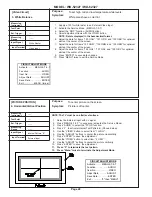
Activating & Selecting an Internal
Test Signal

1. Select an External Input with no signal.
2. Press the buttons “MENU”-“5”-“7”-“5”-“7” in

sequence. (Activates the Service Menu)

3. Select the “FPGA” function (AUDIO button)
4. Press “1” for Pattern A, or “2” for Pattern B.
5.

Press “9”

 to return to the Service Menu.

6. Press “MENU” to exit the Service Mode.

.

CAUTION
DO NOT

 press 

“MENU” (or HOME)

  without

pressing 

“9”

 first.  (The Video Mute function will

not function properly.)

To correct the Mute function

 -- remove AC to

the TV, then reapply AC to reset the unit.

Summary of Contents for WD-52327

Page 1: ... Usage 200W Light Engine DLP 1280 x 720p pixels Light Source 120W VIP Frequency Range VHF 54 470MHz UHF 470 806MHz Antenna Input VHF UHF 75Ω unbalanced 2 NTSC Cabinet Dimensions WD 52327 37 2 H x 49 6 w x 17 4 D WD 62327 43 7 H x 58 3 W x 19 9 D Weight WD 52327 110 lbs WD 62327 139 lbs Speakers 8 Ohms 10W 2 5 inch Coaxial Input Level VIDEO IN JACK RCA Type 1 0Vp p 75Ω unbalanced AUDIO IN JACK RCAT...

Page 2: ......

Page 3: ...Installation of the Lenticular Screen and Fresnel Lens 19 ELECTRICAL ADJUSTMENTS Equipment 20 Initial Setup Option Menu 21 Main Menu Defaults 21 A V Memory Defaults 22 LED Indications 22 LED Dignostic Check 23 Circuit Adjustment Mode 23 Adjustment Items List 25 Activating Internal Test Patterns 26 Adjustment Procedures 27 Main Sub Y level adjustments 27 Main Sub Color level adjustments 27 White Ba...

Page 4: ...lies 43 Video Color Signal Path 44 Sound Signal Path 45 Sync Signal Path 46 Control Circuit Commands Serial Data Reset 47 Control Circuit Status Inputs OSD Insert CCD Insert 48 PWB FORMAT Block Diagram 49 SCHEMATIC DIAGRAMS BLOCK PWB INTERCONNECTIONS S1 1 ...

Page 5: ...ts 2 Electrical parts Block diagrams of the above listed models are included in this service manual for better understanding of the circuitry PRODUCT SAFETY NOTICE Many electrical and mechanical parts in television receivers have special safety related characteristics These charac teristics are often not evident from visual inspection nor can the protection afforded by them necessarily be obtained...

Page 6: ...o the AC plug and touch the other lead to each exposed metal part i e antennas handle bracket metal cabinet screw heads metal overlay control shafts etc particularly any exposed metal part that has a return path to the chassis The resistance of the exposed metal parts having a return path to the chassis should be a minimum of 1Mega Ohm Any resistance below this value indicates an abnormal conditio...

Page 7: ...crews a to remove the COVER FRONT 3 Remove screws b on the rear of the upper back cover 4 across the top and 3 on each side 4 Remove the 4 screws c holding the bottom of the Screen Assembly 5 Unplug connector LN from the Control Panel 6 Lift the Screen Assembly up slightly then pull towards the front to remove the assembly Refer to the Parts List for Part Numbers ...

Page 8: ...ACK from the cabinet REAR DISASSEMBLY FILTER COVER Removal Remove 2 screws d to remove the Filter Cover Rear Plate Removal 1 Remove 6 screws a 2 Remove 6 screws b 3 Pull the COVER BACK from the cabinet 4 Lay the Rear Plate down behind the TV NOTE To operate the TV with the COVER BACK removed the FILTER COVER must be reinstalled ...

Page 9: ...al Procedure 1 Disconnect all relay connectors shown below JE CC JJ PP LL EE 2 Disconnect the J9 and DVI connectors at the Optical Engine 2 Remove three screws a securing the chassis 3 Carefully slide the chassis from the cabinet CHASSIS REMOVAL ...

Page 10: ...Page 10 MODEL WD 52327 WD 62327 Shield Removal 1 To remove SHIELD COVER remove 11 screws a 2 To remove PWB TERMINAL COVER remove 9 screws b ...

Page 11: ...MODEL WD 52327 WD 62327 Page 11 VK26 Chassis PWB Locations Shield Cover removed ...

Page 12: ...rt Rear View 1 Remove theAir Filter 2 Remove the 3 screws a 3 Lift the upper cabinet slightly to remove the support bracket Removing the Lamp Ballast Shield 4 screws Unplug CJ3 CN2 Connectors 4 Screws Unplug Connectors a Lift upper cabinet slightly to remove support Remove Air Filter ...

Page 13: ...m plate with 4 screws b 2 The Black Bracket is secured to the bottom plate and the Lamp Cartridge Housing with 4 screws c 3 Tab 1 on the bottom plate slides into slot 1 on the Adjuster assembly 4 4 screws a secure the bottom plate and Optical Engine to the Adjuster assembly 5 The Optical Engine the bottom plate black bracket and the Optical Engine are removed as a unit ...

Page 14: ...e Engine and the PWB FORMAT 3 From the rear of the TV remove the 4 screws c to remove the COVER DUCT and DMD Fan cover 4 From the rear of the TV remove the 4 screws a shown below securing the bottom plate to the Adjuster assembly 5 Slide the Optical Engine PWB DMD and bottom plate towards the rear to remove the unit from the TV a Optical Engine Rear View Airduct DMD Fan Cover Removed ...

Page 15: ... screw a on the top of the DMD Fan 2 Set the Thermal Sensor aside to install on the replacement Optical Engine Figure 1 DMD Thermal Sensor Bottom Plate Black Bracket Removal 1 Remove the 4 screws B from the Bottom Plate Figure 2 2 Remove the two screws c holding the Black Bracket to the Lamp Cartridge Housing Figure 3 Figure 2 Bottom Plate a Heat Sensor B Bottom View Bottom Plate Thermal Sensor ...

Page 16: ...he Thermal Sensor from the original Optical Engine on the replacement Engine 2 Reverse the removal procedure to install the replacement Optical Engine in the cabinet 2 The following adjustments may have to be performed after the installation Horizontal and Vertical Electrical Centering Adjustment Optical Unit Rotation Adjustment Optical Unit Keystone Distortion Adjustments ...

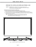
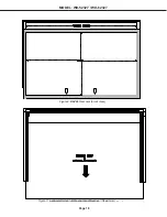
Page 17: ...ly procedure 2 Remove the four screws a to remove the bottom of the SCREEN FRAME BOTTOM Figure 1 3 From the front of the screen assembly slide the BEZEL out the bottom of the Screen Frame Figure 2 4 From the rear of the screen assembly carefully slide the Lenticular Screen and Fresnel Lens combination from the Screen Frame Figure 3 Note When separating the Lenticular Screen from the Fresnel Lens u...

Page 18: ...Page 18 MODEL WD 52327 WD 62327 Figure 3 Lenticular Screen Fresnel Lens Removal Rear View Figure 2 BEZEL Removal Front View ...

Page 19: ...elow Refer to the table below for the tape length 2 Sandwich the Fresnal Lens and Lenticular Screen together The Lenticular Screen label must be towards the front and the Fresnel Lens label towards the rear Figure 4 3 Apply pressure at the top edge to bond the screens together 4 Reverse the Screen Removal procedure and insert the screens in the Screen FameAssembly Figure 4 Installing the Fresnel L...

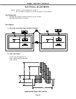
Page 20: ...r equipment is not available Test Equipment Oscilloscope Unless otherwise specified use 10 1 probes Signal Generator NTSC Color Bar Test Signals A Internally Generated Square Pattern Signals B Color Bar Signal Use the color bar signal shown below unless otherwise specified in this manual 1H 40 40 100 75 Split FieldColorBars 100 window ...

Page 21: ...V Chip Start Time 12 00am Listen To Stereo Clock Setting Manual Level Sound Off Clock Time Color Balance TV Volume 30 Set Day Sunday Timer Time Zone N A Video Mute On Contrast 50 Daylight Savings N A Black Enhancementt On Brightness 50 Sharpness 50 Closed Captions In Mute Ant A Auto Color Correction Off Color 50 CC Background Gray PerfectColor Tint 50 Reset Color for Ant A Color Temp High Antenna ...

Page 22: ...gh High Video Noise Standard Standard Standard Standard Standard Film Mode On On On On On Bass Center Center Center Center Center Treble Center Center Center Center Center Balance Center Center Center Center Center Surround Off Off Off Off Off Listen To Stereo N A N A N A N A Level Sound Off Off Off Off Off A V Memory Defaults Normal LED Indications Power Timer Status Lamp Condition Off Off Off Of...

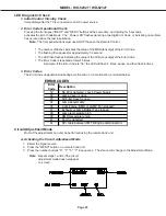
Page 23: ... a total of 5 times Example If the Error Code is 34 the LED will flash 3 times pause and then flash 4 times 3 Error Codes The Error Code designations indicating a malfunction or no malfunction are listed below Circuit Adjustment Mode Most of the adjustments can only be performed using the remote hand unit A Activating the Circuit Adjustment Mode 1 Select the signal source 2 Press the MENU button o...

Page 24: ... Item The Item number increases each time the VIDEO button is pressed C Changing Data After selecting an adjustment Item use the ADJUST UP DOWN buttons to change data Press ADJUST DOWN to decrease the data value Press ADJUST UP to increase the data value D Saving Adjustment Data Press ENTER to save adjustment data in memory The character display turns red for approximately one second in this step ...

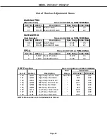
Page 25: ...00 400 128 GBL Low Temp Blue Gain 2D4 2C0 NOTE Data values are in hexadecimal format Initial Data List of Service Adjustment Items MAIN MATRIX Main Decoder Stored in IC2K02 on PWB TERMINAL Item No Abbrev Description Data Range Initial Data 39 SCNT Main Y Gain 0 31 16 41 SCLR Main CB CR Gain 0 31 22 SUB MATRIX Sub Decoder Stored in IC2K02 on PWB TERMINAL Item No Abbrev Description Data Range Initia...

Page 26: ...es the Service Menu 3 Select the FPGA function AUDIO button 4 Press 1 for Pattern A or 2 for Pattern B 5 Press 9 to return to the Service Menu 6 Press MENU to exit the Service Mode CAUTION DO NOT press MENU or HOME without pressing 9 first The Video Mute function will not function properly To correct the Mute function remove AC to the TV then reapply AC to reset the unit ...

Page 27: ...ect adjustment Item 39 SCNT VIDEO button 11 Adjust the data to equal the MAIN Y Gain 0 0V 0 05V 12 Press ENTER to save data changes To set the sub picture color level Main and sub pictures color levels differs Video Circuit 2 Main Sub Color Level Oscilloscope 200mV div 20usec div Color Bars Video Input 1 Supply a color bar signal to a Video Input 2 Select the color bar signal as the source for bot...

Page 28: ...justment 11 Press 9 to terminate the test pattern 12 Press Menu twice to terminate the Adjustment Mode CIRCUIT ADJUST MODE Activate MENU 5 7 5 7 Function AUDIO Item No VIDEO Adjust Data ADJUST Save Data ENTER Exit 9 then MENU White Raster Video Input Video Circuit 3 White Balance To set high mid and low temperature white levels White areas have a color tint 1 Supply a 100 white raster to an Extern...

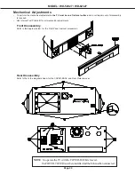
Page 29: ...sembly is required Use internal Test Pattern B for all mechanical adjustments Front Disassembly Refer to the diagram below for the Front Panel removal procedures Rear Disassembly Refer to the to the diagrams below for the COVER BACK and Rear Plate removal NOTE To operate theTV with the COVER BACK removed theFILTER COVERmustbereinstalledandtheExhaustFanconnected ...

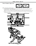
Page 30: ...r Assembly Figure 4A Use a 10mm wrench 2 From the rear of the TV access the black Rotation Adjustment screw and adjust so the test pattern center lines are parallel to the sides top and bottom of the screen frame Figure 4B Use a mirror to veiw the picture from the rear of the set 3 Tighten the two Locking Screws Use Locktite to secure the Adjustment Screw If necessary use the electrical adjust men...

Page 31: ...rizontal Keystone Adjustment for minimum distortion 3 From the front of the TV adjust the Vertical Keystone Adjustment for minimum distortion 4 Tighten the Keystone Lock Screws and secure the adjustment screws with Locktite If necessary use the electrical adjustments to center the picture Horizontal Keystone Distortion Vertical Keystone Distortion Vertical Keystone Adjust Horiz Keystone Adjust Loc...

Page 32: ...4C148001 934C148001 Audio PW B ASSY PW B AUDIO 934C149001 934C149001 Remote Preamp ASSY PW B PREAMP 935D811001 935D811001 Front PWB ASSY PW B FRONT 935D812001 935D812001 Control PWB ASSY PW B CONTROL 935D813001 935D813001 Right Speaker PWB ASSY PW B SPEAKER R 935D814001 935D814001 Left Speaker PWB ASSY PW B SPEADER L 935D815001 935D815001 Lamp Fan FAN LAMP 299P282010 299P282010 DMD Fan FAN DMD 299...

Page 33: ...1566I5M 2 5TR IC8E04 271P010010 IC RT9172 18CG IC8E05 271P010010 IC RT9172 18CG IC8H01 271P113010 IC XC2S50E 6PQ208C IC8H02 271P114020 IC XCF01SVO20C K261 IC9A10 267P175010 HIC STR W6735 IC9A12 271P081010 IC BA00CC0WFP IC9A20 270P816010 IC NJM431L IC9A21 270P991010 IC IRU3037CS IC9AAA 270P677010 IC BA033FP IC9C01 270P928010 IC BA17809FP IC9C11 270P928010 IC BA17809FP IC9C20 267P164010 HIC TNY264P ...

Page 34: ...OIL PEAKING 15MH K L2P25 325C462020 COIL PEAKING 56MH K L2P31 325C462020 COIL PEAKING 56MH K L2P32 325C461050 COIL PEAKING 15MH K L2P41 325C462020 COIL PEAKING 56MH K L2R28 325C461030 COIL PEAKING 10MH K L3A10 409P923060 EMI F CHIP BLM21B272S L3A49 409P923060 EMI F CHIP BLM21B272S L3E25 325C502010 COIL CHIP SLF12575T 330M3R2 H L3E26 325C502010 COIL CHIP SLF12575T 330M3R2 H L3E51 411D009020 CORE FE...

Page 35: ...17 409P876020 EMI F CHIP CNF20C470S CKD510JB1H470S LC1A18 409P876020 EMI F CHIP CNF20C470S CKD510JB1H470S LC1A19 409P876020 EMI F CHIP CNF20C470S CKD510JB1H470S LC1A20 409P876020 EMI F CHIP CNF20C470S CKD510JB1H470S LC2A21 409P875090 EMI F CHIP ELKE103FA LC2A24 409P876020 EMI F CHIP CNF20C470S CKD510JB1H470S LC2A25 409P876020 EMI F CHIP CNF20C470S CKD510JB1H470S LC2A26 409P876020 EMI F CHIP CNF20C...

Page 36: ...P401050 1 10W 150 J 103P494030 1 16W 5 6K F 103P490050 1 16W 150 F 103P503040 1 16W 5 6K J 103P501050 1 16W 150 J 103P503050 1 16W 6 8K J 103P501060 1 16W 180 J 103P503060 1 16W 8 2K J 103P501070 1 16W 220 J 103P494080 1 16W 9 1K F 103P470090 1 8W 220 F 103P494090 1 16W 10K F 103P491000 1 16W 240 F 103P503070 1 16W 10K J 103P501080 1 16W 270 J 103P495010 1 16W 12K F 103P401080 1 10W 270 J 103P5030...

Page 37: ...0V 0 047M J C1B13 181P355090 C ELEC 50V 100M M C1B21 181P352040 C ELEC 16V 100M M C1B24 181P352040 C ELEC 16V 100M M C1B26 172P262010 C M POLY 50V 0 047M J C2AGC 155P239040 C CER CH50V 100P J C2AGD 142P024060 C CER BF50V 0 1M Z C2AJB 142P024060 C CER BF50V 0 1M Z C2AJD 155P239040 C CER CH50V 100P J C2AKC 181P352040 C ELEC 16V 100M M C2AKD 155P239040 C CER CH50V 100P J C2ANC 142P024060 C CER BF50V ...

Page 38: ...H450V 150M M 105C C9A05 189P185090 C CER AC250V E2200P M C9A06 189P185090 C CER AC250V E2200P M C9A08 189P185090 C CER AC250V E2200P M C9A09 189P185090 C CER AC250V E2200P M C9A10 189P185090 C CER AC250V E2200P M C9A11 189P185090 C CER AC250V E2200P M C9A12 189P153010 C M POLY AC125 250V 0 33M M C9A13 189P152070 C M POLY 250VAC 0 01M M C9A14 189P152070 C M POLY 250VAC 0 01M M C9A15 189P185070 C CE...

Page 39: ... 623D252010 MIRROR HOLDER BOTTOM b 622C220010 COVER LAMP VENT 622C247010 COVER SW 635B114010 MIRROR BRACKET TOP a 635B114020 MIRROR BRACKET TOP b 635B115010 FRAME LOCK PLATE a 635B115020 FRAME LOCK PLATE b 641B991010 MIRROR HOLDER SIDE a 641B993010 COVER FRONT 641B999010 MIRROR HOLDER SIDE b 704B205010 KNOBCONTROL a 704B205020 KNOBCONTROL b 704B207010 BUTTON RESET 752B142010 COVER FILTER 752B14301...

Page 40: ...001 ASSY PWB AUDIO 935D811001 ASSY PWB PREAMP 935D812001 ASSY PWB FRONT 935D813001 ASSY PWB CONTROL 935D814001 ASSY PWB SPEAKER R 935D815001 ASSY PWB SPEAKER L 955B310001 ASSY CHASSIS COSMETICPARTS 760A016010 INLAY TERMINAL 761A233010 GRILLE SPEAKER a 761A239010 GRILLE SPEAKER b 775B142080 NAME PLATE WD 52327 a 775B142090 NAME PLATE WD 62327 b 850C095010 INLAY FRONT ACCESSORIES 246C351050 CORD AC ...

Page 41: ...EEN FRAME BOTTOM 7 761A238030 SCREEN COVER TOP 8 768C082010 SCREEN CAP CORNER LEFT 9 768C082020 SCREEN CAP CORNER RIGHT 10 761A252010 BEZEL FRONT 11 623D209010 SHEET BOTTOM WD 62327 1 491P175020 LENS FRESNEL 2 491P176040 SCREEN LENTICULAR 3 623D253010 SCREEN HOLDER 4 701B525010 SCREEN FRAME TOP 5 701B526030 SCREEN FRAME SIDE 14 704B208010 SCREEN TRIM LEFT 15 704B208020 SCREEN TRIM RIGHT 6 761A2420...

Page 42: ...Page 42 MODEL WD 52327 WD 62327 ...

Page 43: ...MODEL WD 52327 WD 62327 Page 43 ...

Page 44: ...Page 44 MODEL WD 52327 WD 62327 ...

Page 45: ...MODEL WD 52327 WD 62327 Page 45 ...

Page 46: ...Page 46 MODEL WD 52327 WD 62327 ...

Page 47: ...MODEL WD 52327 WD 62327 Page 47 ...

Page 48: ...Page 48 MODEL WD 52327 WD 62327 ...

Page 49: ...MODEL WD 52327 WD 62327 Page 49 ...

Page 50: ...Page 50 MODEL WD 52327 WD 62327 ...

Page 51: ......

Reviews: