5
A
B
c
b
a
d
e
f
g
h
i
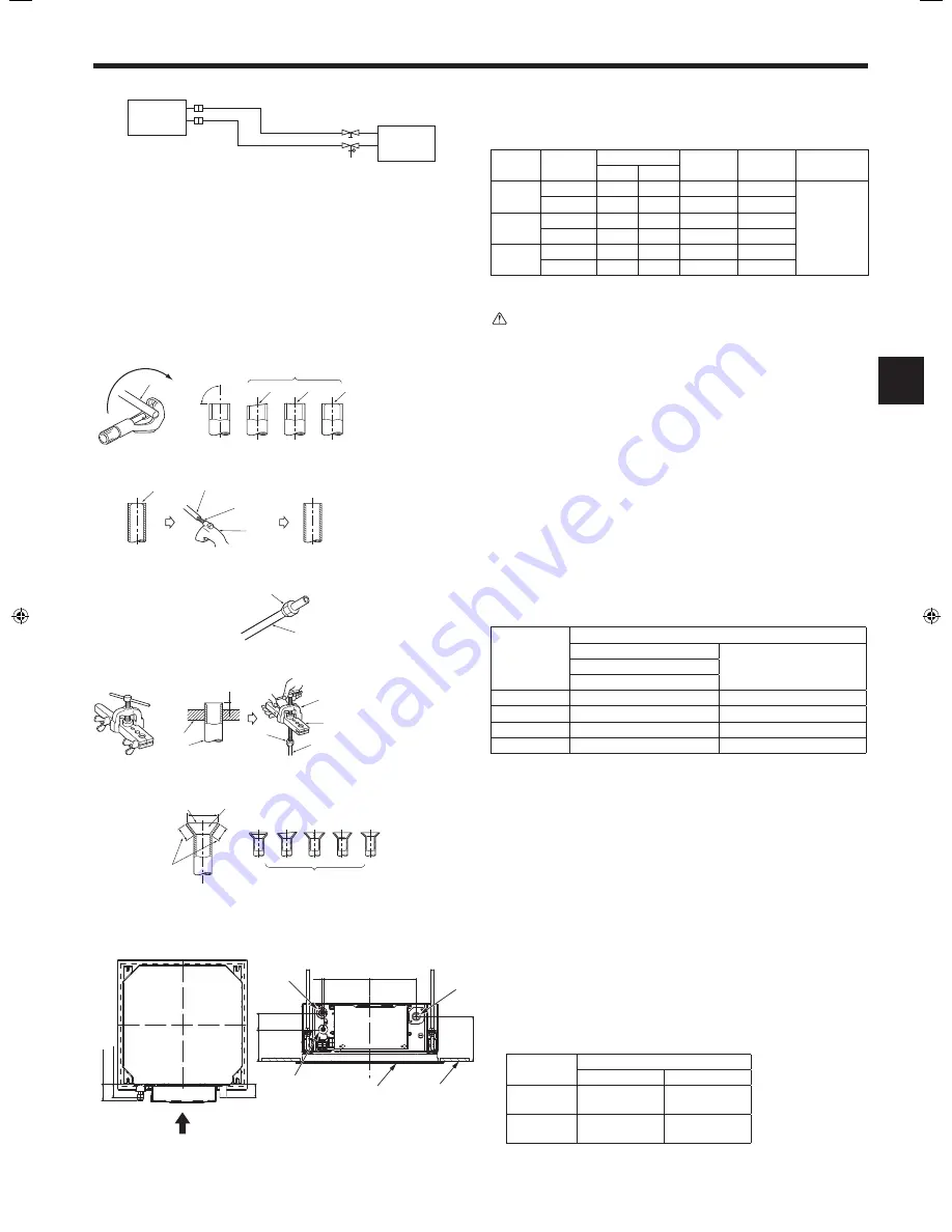
5. Refrigerant piping work
A
Indoor unit
B
Outdoor unit
ø6.35
SLZ-KF25, KF35: ø9.52
SLZ-KF50: ø12.7
SLZ-KF60: ø15.88
Fig. 5-1
5.2. Flaring work
• Main cause of gas leakage is defect in flaring work.
Carry out correct flaring work in the following procedure.
5.2.1. Pipe cutting (Fig. 5-2)
• Using a pipe cutter cut the copper tube correctly.
5.2.2. Burrs removal (Fig. 5-3)
• Completely remove all burrs from the cut cross section of pipe/tube.
• Put the end of the copper tube/pipe to downward direction as you remove burrs in
order to avoid burrs drop in the tubing.
5.2.3. Putting nut on (Fig. 5-4)
• Remove flare nuts attached to indoor and outdoor unit, then put them on pipe/tube
having completed burr removal.
(not possible to put them on after flaring work)
5.2.4. Flaring work (Fig. 5-5)
• Carry out flaring work using flaring tool as shown at the right.
Pipe diameter
(mm)
Dimension
A (mm)
B
+0
-0.4
(mm)
When the tool for R410A is used
Clutch type
6.35
0 - 0.5
9.1
9.52
0 - 0.5
13.2
12.7
0 - 0.5
16.6
15.88
0 - 0.5
19.7
Firmly hold copper tube in a die in the dimension shown in the table at above.
5.2.5. Check (Fig. 5-6)
• Compare the flared work with a figure in right side hand.
• If flare is noted to be defective, cut off the flared section and do flaring work
again.
a
Smooth all around
b
Inside is shining without any scratches
f
Scratch on flared plane
g
Cracked
c
Even length all around
d
Too much
h
Uneven
i
Bad examples
e
Tilted
5.3. Refrigerant and drainage piping locations (Fig.5-7)
A
Drain pipe
B
Ceiling
C
Grille
D
Refrigerant pipe (liquid)
E
Refrigerant pipe (gas)
F
Main unit
Model
Dimension
A (liquid)
B (gas)
SLZ-KF25
SLZ-KF35
63 mm
72 mm
SLZ-KF50
SLZ-KF60
63 mm
78 mm
a
Copper tubes
b
Good
c
No good
d
Tilted
e
Uneven
f
Burred
Fig. 5-2
Fig. 5-3
a
Burr
b
Copper tube/pipe
c
Spare reamer
d
Pipe cutter
Fig. 5-4
Fig. 5-5
Fig. 5-6
a
Flare nut
b
Copper tube
a
Flaring tool
b
Die
c
Copper tube
d
Flare nut
e
Yoke
B
a
d
c
b
e
f
90
d
c
b
a
b
a
a
b
e
b
c
d
c
A
5.1. Refrigerant pipe (Fig. 5-1)
Piping preparation
• Refrigerant pipes of 3, 5, 7, 10 and 15 m are available as optional items.
(1) Table below shows the specifications of pipes commercially available.
Model
Pipe
Outside diameter
Min. wall
thickness
Insulation
thickness
Insulation
material
mm
inch
SLZ-KF25
SLZ-KF35
For liquid
6.35
1/4
0.8 mm
8 mm
Heat resist
-
ing foam
plastic 0.045
specific
gravity
For gas
9.52
3/8
0.8 mm
8 mm
SLZ-KF50
For liquid
6.35
1/4
0.8 mm
8 mm
For gas
12.7
1/2
0.8 mm
8 mm
SLZ-KF60
For liquid
6.35
1/4
0.8 mm
8 mm
For gas
15.88
5/8
0.8 mm
8 mm
(2) Ensure that the 2 refrigerant pipes are well insulated to prevent condensation.
(3) Refrigerant pipe bending radius must be 100 mm or more.
Caution:
Using careful insulation of specified thickness. Excessive thickness prevents
storage behind the indoor unit and smaller thickness causes dew drippage.
Fig. 5-7
6
196
196
188
133
69
64
A
C
E
F
D
B
B
(gas)
A
(liquid)
BH79A235H02_en.indd 5
4/5/2016 4:39:06 PM


