


– 5 –
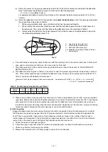
(4) Chain drive
Adjust the chain length so that a slight slackness is formed when the gears are aligned. The shaft-to-shaft distance
should be larger than the diameter of the larger gears plus the diameter of the smaller gears. Consult with the chain
manufacturer for the max. speed ratio and chain lubrication, etc.
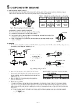
(5) Coupling with internal shaft by key
If the shaft is fitted loosely in the hole, rotary eccentric load will be generated, and creep may occur on the fitting
surfaces of the motor bearing. It is recommended that the gap between the fitting surfaces be 0.03 mm or less as a
difference in diameter.
(6) Other precautions
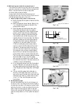
a. The balance of the items fixed to the motor shaft such as the pulley, coupling, gears, fan and impeller must be
within G2.5 specified in JIS B 0905 (balance of rotation devices) when measured with a balancing machine
(rotor balancing machine).
The motor will abnormally vibrate if the balance is incorrect.
(Note) 1. Rusting of the outer bearing ring and wearing of the housing is caused by repeated fine friction of the
bearing engagement section. This is caused by an unbalance.
2. Take note to the tolerable center runout of commercial flexible couplings.
b.
If the pulley or coupling is hammered hard to fit it to the motor shaft, the bearing may be damaged.
When the shrinkage margin with the shaft is large, shrink-fit it. To fit the shaft end key, use a vinyl hammer. (An
iron hammer will give a high impact and may damage the bearing.)
c. If a rust preventive agent with high rust prevention ability has been applied to the motor output shaft and
attached key, remove the agent prior to use.
6
. APPLICATION OF BELTS AND PULLEYS
If the selection of the belt and belt tensioning method are mistaken when coupling the motor and partner machine with
a belt, an excessive force could be applied on the shaft end and bearings, and the life may be shortened and damage
could occur. Observe the following points when making the selection and installing.
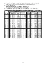
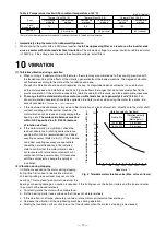
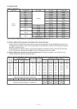
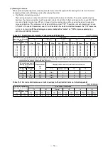
(1) The application of the motor side V-pulley and V-belt is as shown in Table 4. If the pulley diameter is smaller or the
number of belts larger than the values given in Table 4 or if the stepped section of the motor shaft and the rim edge
of the pulley are not on the same plate, confirm that the belt load is lower than the motor's tolerable radial load. If
the belt load is larger than the motor's tolerable radial load, reselect motor or the pulley and belt combination. The
relation of the force applied on pulley and motor shaft is as follows.
Relation of force applied on pulley diameter and shaft
………The larger the diameter is, the smaller the force applied on the shaft will be.
Relation of force applied on pulley width and shaft stepped section
………The larger the width is, the greater the force applied on the shaft stepped section will be.
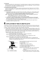
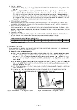
Relation of force applied on pulley axial center and shaft stepped section
……… The greater the clearance between the center and shaft stepped section is, the greater the force
applied on the shaft stepped section will be. (Install so that the motor shaft stepped section and pulley
rim edge is on the same plate. (Refer to Fig. 5.))
[Supplement] Formula for estimating axial load Fs by belts
Fs = 2×N×(16×Td-Y) ×sin(
φ
/2)
N : Number of belts
Td : Deflection load (N) (Refer to Table 4.)
Y : Coefficient according to the kind of V-belt
A(14.7), B(19.6), C(29.4), D(58.8), 3V(19.6), 5V(49)
φ
: Contact angle (Refer to Table 3.)
Remarks 1. For more information, refer to Technical Data No.108
issued by The Japan Electrical Manufacturers'
Association.
2. For the allowable radial load at the shaft end, refer to
Section "Technical Information" in the general catalog.
PW
t = PW
2
Load point
Motor shaft
V-pulley
Ventilation hole
Fig. 5 Installation of pulleys