


– 4 –
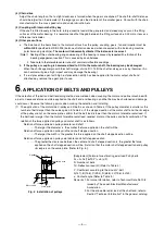
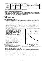
(b) Obtain the center of t, apply a perpendicular load to the V-belt at this center point, and obtain the deflection
force Td (N) where the deflection amount
δ
at that point is the following value.
δ
= 0.016 × t (mm) (Refer to Fig. 4.)
For example, the deflection amount for a distance of 1m between the belt contact would be 0.016 ×1000 =
16 (mm).
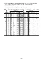
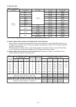
(c) Obtain the deflection force Td (N) for each belt, and
adjust the belt tension so that the average value enters
the range of the values given in Table 4.
1. When using multiple V-belts, use a matched set that has the same belt lengths.
2. When running the motor after mounting a new belt, the belt will elongate after two to eight hours and
become loose. Thus, adjust with the retensioning deflection force (Td) according to Table 4.
3. Always adjust the belt after it has been replaced. If an old belt is used for the replacement, adjust with
the retensioning deflection force (Td).
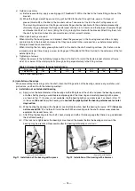
e. If the belt slackens during use, adjust the tension with the adjusting bolt on the motor's slide base. If the flat belt
slips, apply a small amount of belt wax. Do not use wax for the V-belt.
f. The pulley selection is often a problem for using the belt drive, so refer to the section "6. APPLICATION OF
BELTS AND PULLEYS."
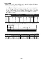
g. The deflection force Td given in Table 4 is the value for when the contact angle between the belt and V-pulley is
140°. If the contact angle changes, multiple the deflection force in Table 4 by the compensation coefficient K in
Table 3, and obtain the deflection force for each.
(
Example
: 55kW, 4-pole, standard V-belt, contact angle 180° : Deflection force Td (180°) = K × Td (140°) = 0.9 × (46 to 53)
≈
41.4 to 47.7 (for new belt tensioning)
)
Table 3 Contact angle compensation coefficient
Contact
angle
φ
140°
150°
160°
170°
180°
K
1.0
0.98
0.94
0.91
0.9
h. When using a V-belt or V-pulley other than that shown in Table 4, the deflection force Td (N) must be calculated
separately. Refer to the Japan Electrical Manufacturers' Association Technical Document No. 108 "V-belt tension
and application" for the calculation method. Be aware that the deflection force (N) specified in the catalogs of
the belt manufacturers may larger than the motor has expected. Depending on the situations, using such catalog
values may lead to damage to the motor bearings or cause the shaft to break.
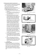
(3) Gear coupling
Engage the gears when the motor and partner machine shafts are parallel. Check the following points to confirm
that the gears are correctly engaged. Note that if the gear diameter is small, bending load may be applied to the
shaft. There is a possibility of generation of high frequency vibration as large as the number of teeth of gear ×
rotation speed (nZ component). Check the vibration (speed/acceleration) to confirm that it is within the standard
range. (Also in the case of use of timing belt, high frequency vibration may occur.)
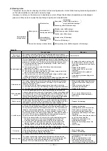
a. Check the centers of both gears aligned.
b. If possible, apply a light coat of red iron oxide, and rotate the gears to confirm that the teeth are contacted.
c. Check any abnormal noise during the rotation.
d. Measure the backlash with a thickness gauge to check that it is adequate.
C
Td
D
d
δ
t
φ
D : Large V-pulley diameter (mm)
d : Small V-pulley diameter (mm)
C : Shaft-to-shaft distance (mm)
Td : Deflection force (N/pcs) (Refer to Table 4.)
φ
: Contact angle
Fig. 4