


24
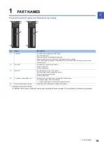
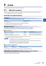
5 WIRING
5.2 External Wiring
5.2
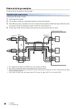
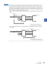
External Wiring
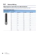
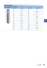
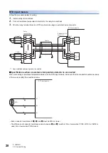
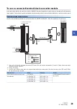
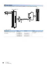
Signal layout of connectors for external devices
The following tables show the signal layout of external device connectors of a temperature input module.
Thermocouple input module
Pin layout (viewed from the
front of the module)
CH1 to CH8, RTD
Pin number
Signal name
Pin number
Signal name
A1
CH1+
B1
CH1-
A2
B2
A3
CH2+
B3
CH2-
A4
B4
A5
CH3+
B5
CH3-
A6
B6
A7
CH4+
B7
CH4-
A8
B8
A9
CH5+
B9
CH5-
A10
B10
A11
CH6+
B11
CH6-
A12
B12
A13
CH7+
B13
CH7-
A14
B14
A15
CH8+
B15
CH8-
A16
B16
A17
B17
A18
B18
A19
B19
RTD+
A20
RTDG
B20
RTD-
B20
B19
B18
B17
B16
B15
B14
B13
B12
B11
B10
B9
B8
B7
B6
B5
B4
B3
B2
B1
A20
A19
A18
A17
A16
A15
A14
A13
A12
A11
A10
A9
A8
A7
A6
A5
A4
A3
A2
A1
Summary of Contents for R60RD8-G
Page 2: ......
Page 14: ...12 MEMO ...
Page 18: ...16 1 PART NAMES MEMO ...
Page 24: ...22 4 PROCEDURES BEFORE OPERATION MEMO ...
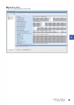
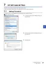
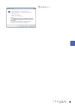
Page 41: ...7 OFFSET GAIN SETTING 7 1 Setting Procedure 39 7 13 Click Yes button ...
Page 47: ...I 45 MEMO ...
Page 51: ......


