94
OPERATING PROCEDURE
PHOTOS
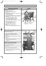
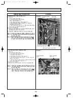
Photo 10
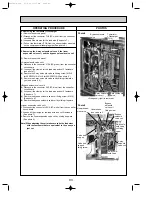
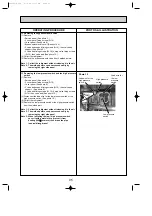
Photo 11
10. Removing the 4-way solenoid valve
(1) Remove
• Service panel (See photo 1.)
• 3 cover panel fixing screws (5
o
10)
• Cover panel (See photo 6.)
• 4-way solenoid valve coil. (See photo 8, 9.)
• 2 valve bed support fixing screws (5
o
10), then valve
bedsupport. (See photo 9.)
• 4 valve bed fixing screws (5
o
10), 4 stop valve fixing screws
(5
o
16), then valve bed (See photo 15.)
(2) Collect the refrigerant.
(3) Remove 4-way solenoid valve together with the pipes from 3
welded points shown in the photo 10.
(4) Separate 4 welded pipes from the 4-way solenoid valve.
Note 1: Collect the refrigerant without releasing it in the air.
Note 2: The welded points can be accessed easily by removing
the right side panel.
Note 3: When installing the 4-way solenoid valve, cover it
with a wet cloth to prevent it from heating (120
;
;
or more), then braze the pipe (non-oxidizing braze).
11. Removing the linear expansion valve
(1) Remove
• Service panel (See photo 1.)
• 3 cover panel fixing screws (5
o
10)
• Cover panel (See photo 6.)
• Linear expansion valve coil (See photo 11.)
• 2 valve bed support fixing screws (5
o
10), then valve bed
support (See photo 9.)
• 4 valve bed fixing screws (5
o
10), 4 stop valve fixing screws
(5
o
16), then valve bed (See photo 15.)
(2) Collect the refrigerant.
(3) Remove the linear expansion valve from 2 welded points.
Note 1: Collect the refrigerant without releasing it in the air.
Note 2: The welded points can be accessed easily by removing
the right side panel.
Note 3: When installing the linear expansion valve, cover it
with a wet cloth to prevent it from heating (120
;
;
or
more), then braze the pipe (non-oxidizing braze).
Bypass solenoid
valve
Thermistor
<Discharge>
3 welded points of the
4-way solenoid valve
4-way solenoid valve
<Side panel (right) is removed>
Linear expansion
valve
Linear expansion
valve coil
OC338C-4.qxp 07.5.24 11:27 AM Page 94

