96
Photo 13
PHOTOS & ILLUSTRATION
OPERATING PROCEDURE
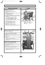
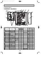
14. Removing the reactor
(1) Remove
• Service panel (See photo 1.)
• 2 screws (4
o
8) that hold the terminal block fixing metal plate
in front of the electrical parts box, then slightly pull the plate
towards you
• 4 screws (4
o
8) that hold the controller circuit board fixing
metal plate in front of the electrical parts box, then tilt the
plate towards you (See photo 6.)
• 3 reactor fixing screws (4
o
8)
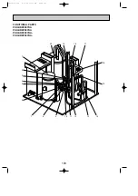
• Remove the reactor by sliding it upward. (See photo 14.)
photo 15
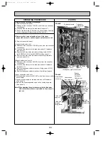
15. Removing the compressor
(1) Remove
• Service panel (See photo 1.)
• 3 cover panel fixing screws (5
o
10)
• Cover panel (See photo 6.)
• 2 valve bed support fixing screws (5
o
10), then valve bed
support (See photo 9.)
• 4 valve bed fixing screws (5
o
10), 4 stop valve fixing screws
(5
o
16), then valve bed (See photo 15.)
• Terminal cover
• 3 lead wire fixing screws (M5
o
10), then disconnect the lead
wire of terminal (See photo 15.)
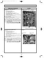
(2) Collect the refrigerant.
(3) Remove the sound insulation.
(4) Disengage the welded points of the compressor inlet and dis
charge pipes.
(5) Remove 3 compressor fixing nuts by using a spanner or a
adjustable wrench.
Note: Collect the refrigerant without releasing it in the air.
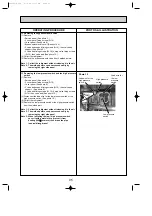
Valve bed fixing
screw
Valve bed
support
Terminal
Compressor
Compressor
fixing nut
(3pcs)
Valve bed
fixing
screw
Valve bed
Photo 14
screws
screws
screws
screws
Reactor
OC338C-4.qxp 07.5.24 11:27 AM Page 96

