91
OPERATING PROCEDURE
PHOTOS
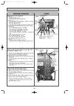
Photo 5
Photo 3
Photo 4
4. Removing the fan motor
(1) Remove
• 14 fan guard fixing screws (5
o
15) (See photo 3.)
• Fan guard by sliding it upward
• Cap by pulling it upward (See photo 4.)
• Propeller fixing nut (M16, left screw)
• Washer (
[
32) and the propeller from the fan motor shaft
(See photo 4.)
• Propeller holding washer (
[
40) from the fan motor shaft
Note 1: Be careful not to drop any of the cap, nuts, and washers
inside the unit.
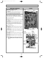
(2) Remove the service panel and the front panel.
(3) Disconnect the relay connector of the fan motor lead wire
in the electrical parts box.
(4) Loosen all the clamps for the fan motor lead wire, and
pull out the wire from the penetration part.
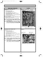
(5) Remove
• 4 motor support fixing screws (5
o
15)
• Motor support together with the fan motor (See photo 4.)
Note 2: The motor support and the fan motor should be held
by two people.
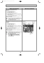
(6) Remove
• 4 fan motor fixing screws (M6
o
16)
• Fan motor (See photo 5.)
Fan guard
Fan guard
fixing
screw
Fan guard
fixing
screw
Service
panel
Unit leg
Front
Propeller
Cap
Motor support
fixing
screw (4pcs)
Fan motor lead wire
Nut tightening torque 20
i
2N•m
Fan motor
Fan motor
fixing screw (4pcs)
Motor support
OC338C-4.qxp 07.5.24 11:26 AM Page 91

