11
䠆
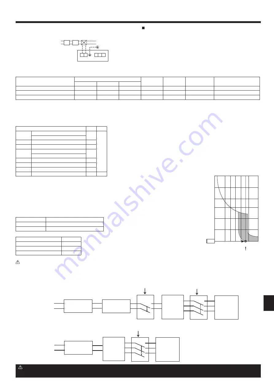
Power supply from Outdoor unit
Power supply
䠆
Supply power separately to branch box and outdoor unit
Power supply
L1
L2
Isolator (Switch)
L1
L2
Outdoor unit
L1
L2
L1
L2
L1
L2
Branch box
S1
S2
S3
S1
S2
S3
"A
-
control
Indoor unit"
3 pole isolator
(Switch)
2 pole isolator
(Switch)
L1
L2
Isolator (Switch)
L1
L2
Branch box
S1
S2
S3
S1
S2
S3
"A
-
control
Indoorunit"
3 pole isolator
(Switch)
L1
L2
Caution:
After using the isolator, be sure to turn off and on the main power supply to reset the system. Otherwise, the outdoor unit may not be able to detect the
branch box(es) or indoor units.
Warning:
In case of A-control wiring, there is high voltage potential on the S3 terminal caused by electrical circuit design that has no electrical insulation between power
line and communication signal line. Therefore, please turn off the main power supply when servicing. And do not touch the S1, S2, S3 terminals when the power
is energized. If an isolator should be used, use the 2 pole type between the outdoor unit and the branch box, and use the 3 pole type between the branch box
and the indoor unit.
8. Electrical work
Power supply wiring (Supply power separately to branch box
and outdoor unit)
• Install an earth line longer than other cables.
• Power supply cords of appliance shall not be lighter than design 245IEC57 or
227IEC57, 245 IEC 53 or 227 IEC 53.
• A switch with at least 3 mm, 1/8 inch contact separation in each pole shall be
provided by the air conditioner installation.
[Fig. 8-10]
A
Ground-fault interrupter
B
Local switch/Wiring breaker
C
Branch Box
D
Pull box
D
C
TB2B
TB5
S
M1
L1 L2
M2
A
B
208/230V
Fig. 8-10
Total operating current of the indoor unit
Minimum wire thickness (mm²/AWG)
Capacity (A)
FUSE (A)
Breaker for wiring
(NFB)
Ground-fault interrupter *1
Main cable
Branch
Ground
F0 = 15A or less *2
2.1/14
2.1/14
2.1/14
15
15
15
15A current sensitivity *3
F0 = 20A or less *2
3.3/12
3.3/12
3.3/12
20
20
20
20A current sensitivity *3
F0 = 30A or less *2
5.3/10
5.3/10
5.3/10
30
30
30
30A current sensitivity *3
Apply to IEC61000-3-3 about max. permissive system impedance.
*1 The Ground-fault interrupter should support inverter circuit.
The Ground-fault interrupter should combine using of local switch or wiring breaker.
*2 Please take the larger of F1 or F2 as the value for F0.
F1 = Total operating maximum current of the indoor units × 1.2
F2 = (V1/C)
Indoor unit
V1
V2
Type 1
SEZ-KD•NA, PLA-A•BA
19.8
2.4
PLA-A•EA
Type 2
PEAD-A•AA5, MVZ-A•AA
26.9
Type 3
MSZ-FE•NA
9.9
Type 4
MSZ-EF•NA, MSZ-FH•NA(2)
6.8
MSZ-GE•NA
Type 5
SLZ-KA•NA
3.5
Type 6
MFZ-KA•NA
16.2
Type 7
MSZ-GL•NA, MFZ-KJ•NA
7.4
Type 8
Branch box (PAC-MKA•BC)
5.1
3.0
C : Multiple of tripping current at tripping time 0.01s
Please pick up "C" from the tripping characteristic of the breaker.
Condition: Branch Box × 2 + SEZ-KD•NA × 5, C=8 (refer to right sample chart)
F2 = 5.1 × 2/8 + 19.8 × 5/8
= 13.65
→
16A breaker (Tripping current = 8 × 16A at 0.01s)
*3 Current sensitivity is calculated using the following formula.
G1 = V2 + V3 × (Wire length[km])
G1
Current sensitivity
30 or less
30 mA 0.1sec or less
100 or less
100 mA 0.1sec or less
Wire thickness (mm
2
/AWG)
V3
2.1/14
48
3.3/12
56
5.3/10
66
6000
600
60
10
Tripping Time [s]
1
0.1
0.01
1
2
Rated Tripping current (x)
3
4
6 8
C
10
20
SAMPLE
Sample chart


