


6
S3
S3
S2
S1
1
S
2
S
L N
2
1
L N
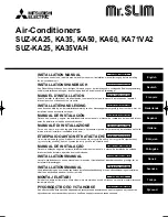
6. Electrical work
Fig. 6-1
Fig. 6-2
Fig. 6-3
Fig. 6-4
6.1. Outdoor unit (Fig. 6-1, Fig. 6-2, Fig. 6-3, Fig. 6-4)
1
Remove the service panel.
2
Wire the cables referring to the Fig. 6-1, Fig. 6-2, Fig. 6-3 and the Fig. 6-4.
A
Indoor unit
B
Outdoor unit
C
Wired main switch/fuse
D
Grounding
For Power supply
Indoor terminal block
Earth wire (green/yellow)
Indoor/outdoor unit connecting wire
3-core 1.5 mm² or more
Outdoor terminal block
Power supply cord SUZ-KA25/KA35: 1.5 mm² or more
SUZ-KA50/KA60/KA71: 2.5 mm² or more
Service panel
Remove fi xing
screw to open the
service panel.
Be sure to fi x the
indoor/outdoor unit
connecting wire us-
ing this cord clamp.
A
Loosen terminal screw
B
Terminal block
C
Lead wire
• Perform wiring as shown in the diagram to the lower left. (Procure the cable locally)
(Fig. 6-2)
Make sure to use cables of the correct polarity only.
A
Connecting cable
B
Indoor terminal block
C
Outdoor terminal block
D
Always install an earth wire longer than other cables.
E
Power supply cord
Caution:
• Use care not to make miswiring.
• Firmly tighten the terminal screws to prevent then from loosening.
• After tightening, pull the wires lightly to confi rm that they do not move.
• Connect cable from the indoor unit correctly on the terminal-block.
• Use the same terminal block and polarity as is used with the indoor unit.
• For aftercare maintenance, give extra length to connecting cable.
• Both end of connecting cable (extension wire) are peeled off. When too
long, or connected by cutting off the middle, peel off power supply cable to
the size given in the fi gure.
• Be careful not to contact connecting cable with piping.
Caution:
• Use care not to make miswiring. (Fig. 6-4)
• Firmly tighten the terminal screws to prevent them from loosening.
• After tightening, pull the wires lightly to confi rm that they do not move.
Warning:
• Be sure to attach the service panel of the outdoor unit securely. If it is not
attached correctly, it could result in a fi re or an electric shock due to dust,
water, etc.
• Tighten terminal screws securely.
• Wiring should be done so that the power lines are not subject to tension.
Otherwise, heat may be generated or fi re may occur.


