1. FUNCTIONS AND CONFIGURATION
1 - 3
Function Description
Detailed
explanation
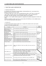
Tough drive function
This function makes the equipment continue operating even under the condition that
an alarm occurs.
The tough drive function includes two types: the vibration tough drive and the
instantaneous power failure tough drive.
"MR-JE-_C
Servo Amplifier
Instruction
Manual"
Drive recorder function
This function continuously monitors the servo status and records the status transition
before and after an alarm for a fixed period of time. You can check the recorded data
by clicking the Waveform-Display button in the drive recorder window of MR
Configurator2.
However, the drive recorder is not available when:
1. You are using the graph function of MR Configurator2.
2. You are using the machine analyzer function.
3. [Pr. PF21] is set to "-1".
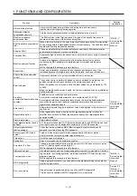
Servo amplifier life diagnosis
function
You can check the cumulative energization time and the number of on/off times of the
inrush relay. This function gives an indication of the replacement time for parts of the
servo amplifier including a capacitor and a relay before they malfunction.
This function is available with MR Configurator2 or via a network. (Refer to section
6.4.)
Power monitoring function
This function calculates the power running energy and the regenerative power from
the data in the servo amplifier such as speed and current. Power consumption and
others are displayed on MR Configurator2.
Machine diagnosis function
From the data in the servo amplifier, this function estimates the friction and
vibrational component of the drive system in the equipment and recognizes an error
in the machine parts, including a ball screw and bearing.
This function is available with MR Configurator2 or via a network. (Refer to section
6.3.)
Modbus/TCP
The Modbus/TCP uses dedicated message frames for the Ethernet communication
between a client (master) and servers (slaves). The dedicated message frames have
functions for reading and writing data, you can set the parameters of servo amplifiers
and monitor it by using this function. In the profile mode, driving the servo motor is
also possible.
Chapter 2
CC-Link IE Field Network
Basic
CC-Link IE Field Network Basic enables fixed cycle communication between the
master and slave stations using a general-purpose Ethernet connector. The
parameters of servo amplifiers can be set (read/written) and monitored. In the profile
mode, driving the servo motor is also possible.
"MR-JE-_C
Servo Amplifier
Instruction
Manual (CC-
Link IE Field
Network
Basic)"
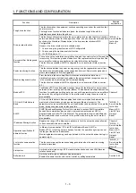
SLMP
SLMP (SeamLess Message Protocol) is a protocol to access SLMP-compatible
devices from external devices (such as a personal computer and an HMI) or
programmable controller CPU via Ethernet. The parameters of servo amplifiers can
be set (read/written) and monitored. In the profile mode, driving the servo motor is
also possible.
IP address filtering function
Register the range of IP addresses in advance to limit the network devices allowed
to be connected to the servo amplifier.
Chapter 4
"MR-JE-_C
Servo Amplifier
Instruction
Manual (CC-
Link IE Field
Network
Basic)"
Operation specification IP
address function
In Ethernet communication (CC-Link IE Field Network Basic, SLMP, or
Modbus/TCP), to limit the network devices to which the operation right is given, set
the range of the device IP addresses.
Monitoring/parameter reading can be performed with the network devices having no
operation right.
Lost motion compensation
function
This function improves the response delay generated when the machine moving
direction is reversed.
"MR-JE-_C
Servo Amplifier
Instruction
Manual"
Limit switch
Limits travel intervals using LSP (Forward rotation stroke end) and LSN (Reverse
rotation stroke end).
Software limit
Limits travel intervals by address using parameters.
Enables the same function with the limit switch by setting parameters.
Section 6.4.5
Summary of Contents for MELSERVO-JE MR-JE-C
Page 9: ...A 8 MEMO ...
Page 83: ...MEMO ...


