English-24
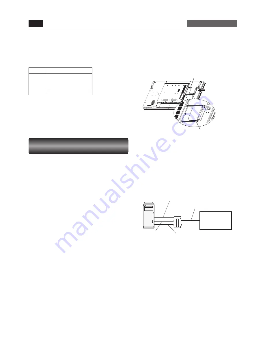
USB cable (commercially available)
CAT5 Tx BOX
(option)
Signal cable (Mini D-SUB 15-pin to Mini
D-SUB 15-pin) (accessory)
CAT5 cable (commercially available)
Computer
Monitor with
CAT5 Rx BOX (option)
RS-232C cable
(commercially available)
* As necessary
CAT5 Rx BOX
Option slot
P-5
Installing the extension module (continued)
Carry out as necessary
Recommended cable:
Coaxial cable having a characteristic impedance of 75 Ω, BNC
connector
Commercially available cable:
1694A of Belden
Input format
SD-SDI
[email protected] Hz, 576i@50 Hz
HD-SDI
720p@50/59.94/60 Hz,
1080i@50/59.94/60 Hz,
1080p@24 Hz
3G-SDI
1080p@50/59.94/60 Hz
Signal system: YC
B
C
R
(4:2:2) / 10 bits only
Removal of the SDI BOX
Hold the handle on the SDI BOX for removal.
CAUTION:
Use the handle to extract the SDI BOX only. Pulling on the SDI
cable (BNC) or by other means may cause damage.
CAT5 for long-distance connection
or multiple-monitor connection
The CAT5 video connection function is for transmitting the
analog RGB video signal of the computer and the control signal
of the monitor over a long distance using CAT5 cables.
The computer can control the monitor via the optional CAT5 Tx
BOX (option) and the CAT5 Rx BOX (option) that is mounted on
MDT551S.
CAUTION:
Never connect network devices (such as a hub and a computer
for LAN) to the CAT5 IN and OUT connectors of the CAT5 Tx
BOX and the CAT5 Rx BOX. If they are connected, the network
devices themselves, CAT5 Tx BOX, CAT5 Rx BOX, and monitor
may be damaged.
1. Installation of the USB driver for CAT5
serial communication control
To connect the computer and the CAT5 Tx BOX (option) via
USB interface, it is necessary to install the USB driver to the
computer from the CD-ROM supplied with the CAT5 Tx BOX.
(Installing the USB driver isn’t necessary when the
communication control isn’t used or the RS-232C cable is used
for connection.)
OS supported: Windows
®
XP, Windows Vista
®
, Windows
®
7
How to install:
Start the “PL2303_Prolifi c_DriverInstaller_v
***
.exe” fi le in the
Windows folder on the CD-ROM supplied with the CAT5 Tx
BOX (option) and install the driver according to the instructions
displayed on the screen.
2. Mounting the CAT5 Rx BOX on the
monitor
1. Turn off the main power switch of the monitor and
disconnect the power cord.
CAUTION:
Be sure to disconnect the power cord to prevent breakdown
and electric shock.
2. Use a Phillips screwdriver to unscrew and remove the
option slot cover.
Retain the screw for later use in step 4.
3. Mount a CAT5 Rx BOX (option) in the option slot of the
monitor.
CAUTION:
To prevent damage, please ensure proper orientation and
position of the CAT5 Rx BOX before inserting it fully into the
slot.
4. Reuse the two screws removed from step 2 and properly
secure the CAT5 Rx BOX.
3. Connection of the CAT5 video
connection function
There are two cases of connection.
1) Connection to one monitor
1. Connect the computer and the CAT5 Tx BOX (option) using
a commercially available USB cable.
2. When the USB connector isn’t used for the communication
control, connect with an RS-232C cable and set the input
selection switch on the CAT5 Tx BOX to the RS-232C side.
NOTE:
To supply a power to the CAT5 Tx BOX, connect a USB
cable also.
3. Connect the analog RGB OUT connector on the computer
and the RGB IN connector on the CAT5 Tx BOX using the
signal cable (mini D-SUB 15-pin – mini D-SUB 15-pin)
supplied with the monitor.
4. Connect the CAT5 output connector (modular connector
8-pin) of the CAT5 Tx BOX and the CAT5 IN connector of the
CAT5 Rx BOX using a commercially available CAT5 cable.


