background image

Chapter 3: NetCommand® Setup and Editing

49

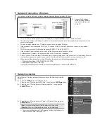
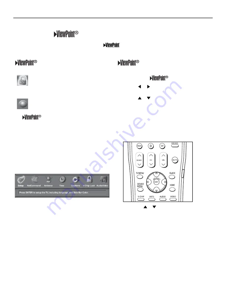
 Remote Control Buttons

The following buttons on your remote control help you 

navigate within the 

 system :

1. ADJUST


  or   to select the menu item you want to 

change.

2. ADJUST   or 

 to change the settings.

3.  ENTER to enter into a menu, start an automatic 

function or select a check box.

4.  CANCEL to clear a setting or stop an automatic 

function.

5.  TV MENU to display the display’s main menu or move 

back one menu screen at a time.

6.  HOME to exit all menus and return to TV viewing.

1"(&

Press ADJUST 

 or 

 to change text boxes.  Some text 

boxes have preset labels. Other boxes allow you to select 
letters, numbers or characters to customize names.

 Menu Screens

A picture (icon) will be highlighted on the 

menu screen when selected with the 

ADJUST arrows.  You may then make 

changes within the menu or access sub-

menus, if available.

You can also access sub-menus from a 

button.  Sometimes when you select a 
button, an automatic function begins.

The 

 system includes the following special 

features:

 •  The currently selected icon or button is  


highlighted with a yellow outline; the text color is 

yellow.

 •  On-screen instructions, shown in the message 

line at the bottom of the menu, provide feature 
selection and adjustment information.

 •  Some on-screen menu options must be set before 

other options are available. 

3D Graphical 

 Menu System

 Main Menu: This screen will always be the first screen that 

appears when you press the remote’s TV MENU button.

Your TV also has Mitsubishi’s exclusive 3D Graphical 

 on-screen operating system, which provides on-screen 

information for menu choices and changes, using the media enter’s remote control.

Summary of Contents for LT-3280

Page 1: ...ner s Guide L LT 3280 LT 3780 T 3280 LT 3780 LCD Flat Panel LCD Flat Panel HDTV HDTV visit our website at visit our website at www mitsubishi tv com www mitsubishi tv com TM TM Display Media Center Display Media Center ...
Page 2: ...the HD 4001 Receiver Controller is referred to as the media center The terms TV and HDTV are used interchangeably to refer to the LCD Flat Panel HDTV To operate as a complete HDTV the display must be connected to the media center using both required MonitorLink cables See Chapter 2 for more information MODEL NUMBER LT 3280 LT 3780 Flat Panel HDTV DISPLAY SERIAL NUMBER MEDIA CENTER SERIAL NUMBER PU...

Page 3: ...14 Media Center Rear Panel 15 Chapter 2 Connecting Essential MonitorLink Connections 18 AC Power Cords 19 External Devices and NetCommand Overview 20 Wall Outlet Cable 21 Cable Box 21 Antenna with Twin Flat Leads 22 Separate UHF and VHF Antennas 22 Using a CableCARD 23 Antenna or Wall Outlet Cable to a VCR 24 Cable Box to VCR 25 A V Receiver or Stereo System 26 Satellite Receiver or Other S Video ...

Page 4: ...ing IEEE 1394 Devices Automatically 53 Device Selection Menu 55 Using the DEVICE MENU Button to Display Menus 56 Device Menu 56 IR Controlled Devices 56 Using the GUIDE Button to Display ChannelView and Menus 57 NetCommand Controlled Recordings 58 Peer to Peer Connections 59 Using A V Discs 60 MediaCommand and Memory Card Playback 61 Direct VCR Recording from an Antenna or Cable Source 63 Chapter ...

Page 5: ...ix B On Screen Information Displays 96 Appendix C Bypassing the V Chip Lock 97 Appendix D Input Connection Compatibility 99 Appendix E Scan Rates for Input Output Sources 100 Appendix F Using PIP and POP 101 Appendix G TV Display and DVD Formats 102 Appendix H Remote Control Programming Codes 104 Appendix I Device Control with NetCommand 107 Appendix J NetCommand Specialized Device Keys 109 Append...

Page 6: ......

Page 7: ...OCK DO NOT REMOVE COVER OR BACK NO USER SERVICEABLE PARTS INSIDE REFER SERVICING TO QUALIFIED SERVICE PERSONNEL Portions of the advanced circuitry of this Media Center must continue to operate even when the Media Center is turned off Some of these circuits therefore need to be cooled at all times A low power standby fan may be heard in a quiet environment This is normal operation WARNING TO REDUCE...

Page 8: ...2 ...

Page 9: ...faces may cause the appliance and cart combination to overturn 7 Ventilation Slots and openings in the cabinet are provided for ventilation and to ensure reliable operation of the LCD Flat Panel HDTV and to protect it from overheating Do not block these openings or allow them to be obstructed by placing the LCD Flat Panel HDTV on a bed sofa rug or other similar surface Nor should it be placed over...

Page 10: ...g the LCD Flat Panel HDTV from the wall outlet and refer servicing to qualified service personnel under the following conditions a When the power supply cord or plug is damaged b If liquid has been spilled or objects have fallen into the LCD Flat Panel HDTV c If the LCD Flat Panel HDTV has been exposed to rain or water d If the LCD Flat Panel HDTV does not operate normally by following the operati...

Page 11: ...es to hold the stand firmly have the other person unscrew the Safety Tab screw See the illustration to the right 7 The person holding the stand can now put the stand carefully in a safe place for future use 8 The display is now ready for mounting Refer to the instructions provided with the Wall Mount Kit purchased separately 5BCMF 1SPUFDUJWF TIFFU JTQMBZ 4UBOE CAUTION A minimum of TWO PEOPLE are n...

Page 12: ......

Page 13: ...ents 8 Special Features 9 Display Top Control Panel 10 Media Center Front Control Panel 11 Remote Control Overview 12 Remote Control Operation 13 Battery Installation 13 Care 13 Sleep Timer 13 Display Rear Panel 14 Media Center Rear Panel 15 ...

Page 14: ...e On Screen Interactive Guide User s Manual not pictured 8 Two AC Power cords One for the display and one for the media center 7 One Digital Audio cable Sends audio from digital TV channels to a digital Audio Video A V Receiver 6 One MonitorLink Control RS 232C cable Sends control signals between the media center and the display allowing IR signals from the remote control and other control signals...

Page 15: ...cable box to access digital cable programming including high definition Contact your local cable provider for availability information and service details NetCommand Home Network Control System Your Mitsubishi media center offers a new level of networking to combine selected older products with new and future digital products NetCommand supports IEEE 1394 connections Audio Video Control system AV ...

Page 16: ... in the lower left corner of the display below the screen as shown in the diagram below IR Sensors The display has two IR sensors one for ordinary TV operation and one for Learning Under normal conditions point the remote at the display and the IR signal will reach both sensors If using the remote close to the TV point the remote control at the sensor you wish to activate For ordinary TV operation...

Page 17: ...ot power Off press the SYSTEM RESET button by inserting a pointed item like the end of a paperclip into the SYSTEM RESET opening The media center will turn Off and the front panel Power Indicator Light will flash quickly for about one minute When the light stops flashing you may again turn on the media center The changes you made the last time the media center was on before you used the SYSTEM RES...

Page 18: ...DEVICE Displays PIP Selection menu to select the PIP or POP image source device 15 REC Record Displays the Record menu for setting up recordings such as recordings for a DVCR or IEEE 1394 devices or while in ChannelView Records with a VCR Starts a recording when the Listings screen for TV Guide On Screen is displayed 16 REW REV Rewinds a VCR Reverses scan with a DVD A V Disc or memory card file 17...

Page 19: ...ity the message box disappears 2 Load the batteries making sure the and polarities are correct For best results insert the negative side first Care For Best Results from the Remote Control Be within 20 feet of the equipment Do not press two or more buttons at the same time unless instructed Do not allow unit to get wet or become heated Avoid dropping on hard surfaces Do not use harsh chemicals to ...

Page 20: ...dia center must be connected using both MonitorLink terminals A and B Remove the covers shown in the lower diagram to access the inputs described on this page A MonitorLink RS 232C Control Use the supplied RS 232C cable to connect the RS 232C terminal on the display A to the RS 232C terminal on the media center A This input only supports the media center B MonitorLink A V Input Use the supplied A ...

Page 21: ...the same time 3 HDMI Input 1 2 Use this input to connect to EIA CEA 861 compliant devices such as a high definition cable box satellite receiver or DVD player This input supports 480i 480p 720p and 1080i video formats It is not intended for use with personal computers or devices outputting video signals with computer resolutions This input can also be used as a DVI connection with separate analog ...

Page 22: ...d in your cable TV subscription without the use of a cable box See page 23 for additional CableCARD information and activation instructions If your cable company is not currently offering CableCARD access cards you will need to use a cable box provided and authorized by your local cable company to view scrambled channels 9 Digital Audio Output This output will automatically send Dolby Digital audi...

Page 23: ...22 Separate UHF and VHF Antennas 22 Using a CableCARD 23 Antenna or Wall Outlet Cable to a VCR 24 Cable Box to VCR 25 A V Receiver or Stereo System 26 Satellite Receiver or Other S Video Devices 26 DVD Player or Other Component Video Device 27 HDMI Output Device 28 DVI Output Device 29 IR Emitters and NetCommand 30 Compatible IEEE 1394 Device 32 Connection Styles 33 Helpful Hints 34 ...

Page 24: ...2 MonitorLink Digital A V cable required and provided The media center is designed specifically to work with the LT 3280 and LT 3780 displays The MonitorLink RS 232C control connection allows the media center to turn the display and media center automatically on or off and control A V devices connected to the media center The MonitorLink Digital A V cable carries video and audio signals from conne...

Page 25: ...s to AC outlets until AFTER all A V devices are connected Instructions for connecting A V devices are provided in this chapter NOTE After a power outage or after the media center power cord has been accidentally unplugged the blue light on the front of the media center will start to blink This is normal the media center is re initializing Wait for the blue light to stop blinking about 1 minute the...

Page 26: ... NetCommand Setup procedures are provided in Chapter 3 which includes the types and brands of devices you are connecting to the media center NetCommand Setup also assigns preset media center and A V receiver inputs for each device Typically each device is connected to the media center input video and to the A V receiver audio as shown in the figure below Connections will vary depending on your req...

Page 27: ...lly for CableCARD use 1 Connect the incoming cable to IN on an RF splitter 2 Connect one coaxial cable from OUT on the RF splitter to ANT 1 MAIN on the media center rear panel 3 Connect one coaxial cable from OUT on the RF splitter to IN on the cable box 4 Connect one coaxial cable from OUT on the cable box to ANT 2 AUX on the media center rear panel Additional connection cables are not provided w...

Page 28: ...se with CableCARD Figure 6 For an antenna with twin flat leads A 300 ohm to 75 ohm transformer is required This is not included with the media center but is available at most electronics stores 1 For antenna with twin flat leads connect the 300 ohm twin leads to a 300 ohm to 75 Ohm transformer purchased separately 2 Push the 75 ohm side of the transformer onto ANT 1 MAIN on the media center rear p...

Page 29: ...luded in your cable TV subscription without the use of a cable box It also allows your cable provider to automatically update and change your subscription When you move to a new cable provider s area you simply return the CableCARD to the original cable provider and get a new card from your new cable provider Please note that CableCARD is a new technology and your local cable provider may not curr...

Page 30: ...controlled recordings connect a set of audio cables from AUDIO IN on the VCR rear panel to MONITOR OUTPUT AUDIO LEFT MONO and AUDIO RIGHT on the media center rear panel The red cable connects to the R right channel and the white cable connects to the L left channel 7 Complete the NetCommand controlled recordings connections by connecting a Video cable from VIDEO IN on the VCR rear panel to MONITOR...

Page 31: ...O RIGHT on the media center rear panel The red cable connects to the R right channel and the white cable connects to the L left channel If your VCR is mono non stereo connect only the white left cable 7 Connect either an S Video or Video cable from VIDEO OUT on the VCR rear panel to INPUT 1 VIDEO on the media center rear panel Only one type of video cable should be connected S Video is recommended...

Page 32: ...MZ JG DPOOFDUJOH B JHJUBM 7 3FDFJWFS 065 69 5 1 5 1 7 3 7 3 7 57 3 165 015 165 0 9 165 0 9 5 6 0 5 6 0 165 0 9 3FE 8IJUF FEJB FOUFS 3FBS 1BOFM 7 3FDFJWFS 065 Figure 10 Connecting an A V receiver Satellite Receiver or Other S Video Devices Figure 11 An S Video cable and audio cables are required These are not included with the TV sytem 1 Connect an S Video cable from VIDEO OUT on the satellite rece...

Page 33: ... quality if your A V receiver supports digital audio connect the DVD Coaxial or Optical digital audio directly to the A V receiver instead of using the L R analog audio ports 7 0 7 0 065 5453 1 5453 1 463306 3 46 800 3 0 9 0 9 015 015 6 0 06 65 546 4 463306 8IJUF 3FE 3FE 8IJUF 7 1MBZFS FEJB FOUFS 065 065 7 0 46 800 3 463306 5P 7 3FDFJWFS VTJOH PBYJBM PS 0QUJDBM EJHJUBM BVEJP DPOOFDUPST JG TVQQPSUF...

Page 34: ...nel to the HDMI output on the source device output HDMI devices provide video and audio through this cable NOTE The HDMI input terminals are compliant with the EIA 861 Standard and are not intened for use with personal computers FEJB FOUFS 065 Z 1 13 0 10 5 7 0 065 4 7 0 065 YYYYYYYYYY YYYYYYYYYY YYYYYYYYYY YYYYYYYYYYYYYYYYYYYYYYYYYYYYY YYYYYYYYYYYYYYYYYYYYYYYYYYYYY YYYYYYYYYYYYYYYYYYYYYYYYYYYYYYY...

Page 35: ...e DVI Analog Audio input on the media center rear panel The red cable connects to the R right channel and the white cable connects to the L left channel NOTE The HDMI connection supports copy protection HDCP Some devices require connecting to an analog input first in order to view on screen menus and select DVI as the ouput Please review your equipment instructions for DVI connectivity and compati...

Page 36: ... panel It is sometimes visible when you look through the display plastic using a flashlight and is normally a round or square cutout behind the plastic If you cannot see the sensor and the device s Owner s Guide does not specify the location you can find it by using the device s remote control Hold the remote about 1 2 inch from the front of the device Starting from one end of the display window p...

Page 37: ... TJOHMF BWFSBHF TJ FE 7 EFWJDF 3 TFOTPS 3 FNJUUFS PO UPQ PG TJOHMF UBMM TJ FE EFWJDF 3 TFOTPS 3 FNJUUFS JO GSPOU TIBSFE CZ UXP BWFSBHF TJ FE 7 EFWJDFT 3 TFOTPS 3 TFOTPS Figure 16 IR Emitter Placement Recommendations IR Emitter Placement Figure 16 ...

Page 38: ...ty to consider are 1 Digital Video Signals The media center is able to decode MPEG2 video Other types of digital video such as DV video provided by some camcorders must be decoded by the source device and sent to the media center as analog video or S Video If the camcorder uses a compatible digital control system the IEEE 1394 cable can still provide control for the camcorder while the display is ...

Page 39: ...n device you will need to connect the camcorder directly to the household AC or use the camcorder s battery for power If this is not possible then the camcorder will need to be connected directly to another 6 pin device in the network that can provide the electrical power QJO UP QJO BEBQUPS 4 pin connector 6 pin connector Direct Device To Device Style The IEEE 1394 offers you the capability to cha...

Page 40: ...s 1 Mount the IR Emitter on the top front edge of the A V Receiver over the remote control sensor Use tape to secure it in place 2 Mount the IR Emitter on the underside of the shelf above the A V Receiver if the A V Receiver is in a cabinet Use double sided tape to secure it in place 3 Some small stick on emitters from other manufacturers may be compatible with this media center s IR Emitter termi...

Page 41: ...etCommand Initial Setup 37 Edit NetCommand 39 Add an A V Receiver 39 Add Devices 42 Change Devices 45 Delete Devices 46 Finish Screen 46 Setup Reminder Screen 46 Using the Remote Control with NetCommand 47 NetCommand On Screen Buttons 48 3D Graphical Menu System 49 3 ...

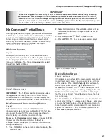
Page 42: ...saves you from having to search for the correct input every time you want to change devices Unused inputs are automatically deactivated so that you don t see them in the menu show an on screen icon for each device connected to the TV so you always know what devices are available Note that with a basic setup you still need to use the remote control specific to each device Limited Setup In a limited...

Page 43: ...e following 1 Press TV MENU on the remote control to display the TV Main menu IMPORTANT To take advantage of the versatility of your new HDTV Mitsubishi recommends that you set up NetCommand as soon as you finish connecting your A V devices and power on the LCD Flat Panel TV for the first time Although setting up NetCommand is optional TV Guide On Screen can not control connected cable boxes or re...

Page 44: ...iew the settings to ensure that they are correct If necessary you can use Back to return to the Device Setup screen to make changes Figure 5 Review screen Note The Review screen lists the media center input and A V receiver input used with each device You must correctly identify the inputs you used when you connected the devices If you have not connected your devices write down these inputs as a g...

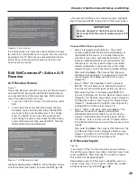
Page 45: ...ter you may use the Change option in the NetCommand menu to learn the remote control signals After selecting Next the screens that follow are the A V Receiver Input screen Figure 8 Name screen Figure 10 Audio Line Out to AVR screen Figure 12 ending with the Finish screen Figure 13 A V Receiver Inputs Figure 8 If you select Other as the manufacturer you will see the A V Receiver Input screen after ...

Page 46: ... receiver automatically switches between analog and digital audio then you don t need to learn either Analog to Digital or Digital to Analog functions A V Receiver Input Learn Screen Figure 9 Figure 9 A V receiver Input Learn screen NetCommand can now learn the remote control signals used to select each input on the A V receiver 1 Press ADJUST or on the TV remote control to select the check box fo...

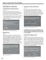
Page 47: ...te the A V receiver setup select Finish from the Finish screen Note If you connected the audio output of any device directly to the A V Receiver you must use the Change function of the Edit NetCommand menu and select the device to assign the correct A V Receiver input to be used with each device Figure 13 Finish screen Add an A V Receiver continued Name Screen Figure 11 The Name screen allows you ...

Page 48: ...settings and connections delete devices and learn remote control IR signals not already in NetCommand memory that will display is the Device Setup Screen See Figure 3 for more information Note If you have completed the NetCommand setup you can access the Edit menu at any time by pressing TV MENU then selecting NetCommand See page 66 for details Use these settings to change the NetCommand setup to ...

Page 49: ...e screens Figures 21 23 ending with the Finish screen Figure 26 Select Other skip Learn and select Next This will allow the device to appear and will allow NetCommand to switch inputs to use this device However NetCommand will not be able to control this device Later you may use the Change option in the Setup menu to learn the remote control signals Device Learn Screen Figure 17 Shown only if Lear...

Page 50: ...ed Learn Screen Figure 18 After learning the basic device keys the Device Advanced Learn screen allows you to learn any special keys for your device Most common IR remote control signal formats can be learned by NetCommand A table of specialized device keys is shown in Appendix J You only need to learn the functions your devices respond to and can ignore the functions that do not apply to your dev...

Page 51: ...tsubishi VCR you can specify the IR Code setting to VCR B if the primary Mitsubishi VCR is using the VCR A IR code Figure 22 IR Code for Device screen Edit NetCommand Change Devices Change Device Screen Figure 24 Selecting Change from the Setup menu screen displays the Change screen To change a device select the device by name not type You can change the name or input connections to the media cent...

Page 52: ... finalize your selections and complete the NetCommand setup select Finish from the Finish screen Note To change any of the inputs or names for the devices or add devices not included in the initial settings select Edit to display the Edit NetCommand menu Figure 26 Finish screen Setup Reminder Screen Figure 27 This screen only appears if you did not set up NetCommand when the TV was first turned on...

Page 53: ...learning feature Bright light near the front of the display can also adversely affect the learning feature If it is not possible to learn a device you will need to use the original remote control of the device or program the TV remote control to operate these devices in the traditional manner NetCommand Pre Memorized Devices DEVICE Manufacturer A V receiver Cable Box SAT Satellite Receiver DVD Pla...

Page 54: ...d Setup screen Highlight the button and press ENTER to select the function NetCommand On Screen Buttons To use the media center s NetCommand feature you need to provide some detailed information during the setup You must define the manufacturer of the devices that are connected to the media center or learn the IR code remote control signals for the device connected For each device the input to the...

Page 55: ...on the menu screen when selected with the ADJUST arrows You may then make changes within the menu or access sub menus if available You can also access sub menus from a button Sometimes when you select a button an automatic function begins The system includes the following special features The currently selected icon or button is highlighted with a yellow outline the text color is yellow On screen ...

Page 56: ......

Page 57: ... 53 Device Selection Menu 55 Using the DEVICE MENU Button to Display Menus 56 Device Menu 56 IR Controlled Devices 56 Using the GUIDE Button to Display ChannelView and Menus 57 NetCommand Controlled Recordings 58 Peer to Peer Connections 59 Using A V Discs 60 MediaCommand and Memory Card Playback 61 Direct VCR Recording from an Antenna or Cable Source 63 4 ...

Page 58: ...mitter for NetCommand in front of the device s remote control sensor see IR Emitters page 30 31 2 On the Name for 1394 Device screen Figure 2 page 53 use ADJUST and ENTER to check mark the Analog Connection box 3 Select the device type on the IEEE 1394 Device Type screen Figure 3 page 54 of DBS Satellite receiver or similar tuning device 4 If desired use the ADJUST buttons enter a custom Name on t...

Page 59: ... VHS in addition to D VHS This allows you to play analog rental tapes or analog tapes from your established library or make analog recordings from antenna or cable systems To use the analog capability check the Analog Connection box Figure 1 New 1394 Device screen Figure 2 Name for 1394 Device screen Adding IEEE 1394 Devices Automatically When an IEEE 1394 device is connected into the media center...

Page 60: ...igures 3 and 4 If the new IEEE 1394 device is also connected using analog inputs you will need to define the device type Select the type of device such as a VCR Figure 3 IEEE 1394 Device Type screen Once the device type is selected then the Device screen is displayed so the manufacturer can be selected If the manufacturer is listed then you may be able to control this device while it is operating ...

Page 61: ... display s internal speakers or A V receiver power compatible devices On or Off and verify the destination of signals On the Device Selection menu the device or input currently displayed appears as a gold colored icon Figure 7 Device Selection Menu with NetCommand Video Section Connection Section Audio Section Device Section If a device does not respond to separate On or Off remote control signals...

Page 62: ...rol s DEVICE MENU button displays the transport menu if the input is a VCR or DVD Another press of the DEVICE MENU button will display menu for the current device source if available Figure 9 Transport menu IR Controlled Devices For a NetCommand compatible traditional IR controlled device pressing DEVICE MENU once or twice will display the menu for that device While the menu for the device is disp...

Page 63: ...mpatible satellite receivers you may also be able to use the number or other additional buttons For NetCommand compatible DVD players GUIDE will display the DVD disc top menu not the setup menu For A V Discs pressing GUIDE will display the Track List screen For IEEE 1394 devices with digital connections press GUIDE twice to display the device s Guide GUIDE and the Device Selection Menu For compati...

Page 64: ... Source Device section 3 Press ADJUST or to select the source device you will record from If a source is not displayed it is not available as a recording source 4 Press ENTER to confirm selection and return to the Record to section 5 In the Record to section review the destination device and duration Use ADJUST or to change if necessary 6 Press REC a second time to initiate recording Time Delayed ...

Page 65: ...the connection between the two devices Once the connection has been established the media center can be turned off or be used to display another device on the monitor Recording from digital channels to a DVCR is also a peer to peer connection In this case the media center is one of the devices in the peer to peer connection NOTE Multiple peer to peer connections can occur simultaneously sometimes ...

Page 66: ...it on the list and press CANCEL Press CANCEL again to confirm A V Disc Search NetCommand is able to search to a specific time in a recording on an IEEE 1394 A V Disc 1 Start the desired track s playback on the A V disc 2 Use the number buttons to enter the time code position of hours followed by minutes For example to enter one hour and twenty two minutes 1 22 into the track enter 1 2 2 3 Press EN...

Page 67: ... track playlist Figure 18 DEVICE MENU to display the Media Setup menu Figure 19 Using Remote Control Buttons for Controlling Playback For JPEG Pictures Slideshow PLAY begins or resumes slideshow playback PAUSE pauses or resumes playback while in the automatic advance mode FF skips to the next slide REW returns to the previous slide FORMAT single press rotates the slide 90 Multiple press continues ...

Page 68: ...e or 2560 x 1920 pixels Pictures will be scaled to the display Some pictures may be cropped to fit 3 Full path file names can be no longer than 50 characters and must end in a jpg extension Not all 50 characters will display For MP3 or WMA7 Audio files 1 Files recorded with sampling rates of 32 kHz 44 1 kHz or 48 kHz 2 Files recorded with fixed bit rates 3 File names with mp3 or wma extensions NOT...

Page 69: ...s not have separate power On and Off features then leave that device powered On Direct VCR Recording from an Antenna or Cable Source Pressing REC record on the media center s remote control will function the same way as pressing the record button on the VCR s remote control or front panel To record directly from antenna or cable 1 Press DEVICE on the media center s remote to display the Device Sel...

Page 70: ......

Page 71: ...enu Choices 66 Setup Menu 67 NetCommand Menu 68 Antenna Menu 69 Time Menu 71 Captions Menu 72 Customizing Digital Settings 73 V Chip Rating Guidelines 74 V Chip Lock Menu 75 V Chip Menu 75 Audio Video Menu 77 A V Setting Descriptions 78 ...

Page 72: ...ected V Chip Lock Menu Figure 6 Block or allow programing based upon rating signals sent by the broadcast station or lock by time Figure 6 Main menu V Chip Lock selected Audio Video Menu Figure 7 Reset the A V Memory to return to the original factory A V settings for a selected device Customize the individual audio and video settings Display a blue screen when viewing a device with no signal Figur...

Page 73: ... other information sent by a broadcaster will be shown in the original language Color Balance Your media center uses six colors Magenta Red Yellow Green Cyan and Blue to create color balance You may adjust the intensity of the colors automatically or manually PerfectColor or reset them to the default settings Each input or device has a memory for PerfectColor Auto Color Balance If the Auto box is ...

Page 74: ...he icon Figure 13 Icon Order Menu Transport Menu Figure 12 Main Picture Figure 12 Transport Menu NetCommand uses the Transport menu to control the VCRs DVDs IEEE 1394 AV Discs digital VCRs and similar devices If you choose to turn off this menu when viewing the devices the transport buttons rewind play forward stop pause and record on the media center s remote control will continue to operate thes...

Page 75: ...V Guide On Screen has been set up Channel Channels can be changed in 3 ways 1 By pressing ADJUST or to select the channel 2 By pressing CH or for channels already in memory 3 Directly entering the number With so many current and potential channels the number range is greatly expanded Channels can be one part analog or digital up to the number 16383 or two part for digital channels these use a sepa...

Page 76: ... on the screen press the CANCEL button If the CANCEL button is not pressed before the SQV indicator disappears automatically the channel will not be removed 4 When the SQV indicator disappears the channel has successfully been removed only from that bank Other banks remain unchanged Antenna Menu continued SQV SuperQuickView Using The Menu Screen Figure 15 SQV SuperQuickView allows you to put toget...

Page 77: ...he correct time and date information from this channel Be aware that if a channel displays incorrect time information it is because of information sent from the broadcaster and is not a defect of the media center Timer On Off Figure 17 The timer can be turned to On or Off When On you need to select the time and day to turn the TV On and the device and channel to display With the TV off and the tim...

Page 78: ...you can choose to display the background color as either black or gray behind the captions Digital Captions The media center can display one of the following Captions for Digital sources Captions 1 6 Sent by broadcaster On if Mute Closed captions when mute When selected the captioning signal Caption 1 will turn on off by pressing MUTE on the HDTV remote control Off No closed captions Note If the b...

Page 79: ... background colors are as follows White Yellow Black Green Magenta Cyan Red Blue Opacity Font You can customize the visibility of your fonts using the following categories Transparent See through text to the TV program Translucent TV program is visible behind the text Opaque Solid color text blocks the TV program Flashing Text flashes in intervals We recommend you use contrasting colors between ca...

Page 80: ...A V Violence graphic or realistic applies in different degrees to TV PG TV 14 and TV MA When you select a TV rating you are selecting the least restricted program level that can be viewed As an example if you select TV PG you are allowing programs rated TV Y TV Y7 TV G and TV PG to be seen and blocking programs rated TV 14 and TV MA When you select a TV Content category you will block all TV progr...

Page 81: ...t pass code using the number keys on the remote control Press CANCEL to delete a number and move back one space Press MENU or HOME to exit without setting a pass code 3 Press ENTER to confirm the pass code just input To reset the pass code see the procedure in Appendix C V CHIP PARENT LOCK To go to the menu enter a new passcode Use the NUMBER buttons and press ENTER Figure 21 The V Chip Parent Loc...

Page 82: ...e a selection 9 Press TV MENU to save the settings and close the menu NOTE To make the V Chip restrictions active twenty four hours a day make the V Chip Start and Stop the same time The V CHIP Button Press the V CHIP button on the remote control to turn the V Chip lock on and off without going through the menu A screen will appear prompting you for your pass code To change V Chip settings you mus...

Page 83: ...e device in A V Memory Reset then select Audio or Video to adjust the device s individual settings Press ENTER the menu is removed and the individual settings are displayed Use the AUDIO and VIDEO buttons on the remote control to change settings as these options are not accessible from this screen Use ADJUST or to select the individual settings for adjustment Use ADJUST or to adjust For descriptio...

Page 84: ...r digital audio formats do not offer this dynamic range control In these cases no effect will be heard when changing the level sound setting A V Setting Descriptions Audio NOTE The effects of the Audio Settings of Bass Treble Balance and Surround affect the sound heard through the display s internal speakers only Using the AUDIO Button on the Remote Control To adjust individual Audio settings dire...

Page 85: ... decoding correction for signals that originated on 24 frames per second film cameras and then were converted for broadcast to 30 frames per second video When the original signals originated on 30 frames per second video cameras the On setting will automatically apply video decoding the same as used with the Off setting Try the Off setting when the TV seems to have difficulties and adds too many j...

Page 86: ......

Page 87: ...Chapter 6 Connecting and Using a PC Connecting a PC to the Display 82 Setting PC Resoluiton 83 PC Display Formats 84 PC Video Settings 85 Supported PC Timings 85 ...

Page 88: ...minal can be used for this purpose Note The display s PC video input is only compatible with VGA SVGA XGA or SXGA resolutions If your PC has digital audio output connect that terminal to a digital input of your digital A V receiver if available The HDTV display and media center only supports analog PC audio 3 Add the device PC in the NetCommand menu 4 Select the PC through the Device Selection men...

Page 89: ...or most PC s Your display can display VGA SVGA XGA and SXGA refresh rates 1 In the PC s Start menu select Settings 2 Select Control Panel 3 Select Display 4 Select the Settings tab 5 Depending on your PC use either the Screen Area slider or the Screen Resolution slider to adjust the resolution You may need to restart your PC for this change to take effect Figure 16 Selecting VGA resolution for a P...

Page 90: ...366 x 768 1366 x 768 LT 3280 Display Displayed Format PC Video Signal SVGA 800 x 600 1366 x 768 LT 3780 Display VGA 640 x 480 XGA 1024 x 768 WXGA 1280 x 768 SXGA 1280 x 1024 PC720P 1280 x 720 1360 x 768 1920 x 1080 1920 x 1080 1920 x 1080 1920 x 1080 1920 x 1080 1920 x 1080 SVGA 800 x 600 1920 x 1080 Displayed Format PC Video Signal 1920 x 1080 1920 x 1080 PC Display Formats ...

Page 91: ...settings Contrast Manually adjusts the contrast of the PC screen image Bightness Manually adjusts the brightness of the PC screen image Back Light Manually adjusts the contrast of the PC screen image Video Clock Manually adjusts the PC clock frequency Horiz Res Horizontal Resolution Manually adjusts the horizontal size of the PC screen image Vert Res Vertical Resolution Manually adjusts the vertic...

Page 92: ......

Page 93: ...Chapter 7 Troubleshooting and Support Troubleshooting 88 Using the System Reset Button 92 Using the Reset Menu 92 Support 92 ...

Page 94: ... operation 7 You cannot program the media center to turn on automatically timer function The media center may be locked The clock may not be set 8 There is no sound even when the volume is turned up Check audio source in Device Menu Check to see if the MUTE button is on The media center s Listen to setting may be set to SAP If you are listening through a DVI device check that the analog audio has ...

Page 95: ...nge the media center NetCommand settings for the connection screen for each device 22 The Device does not respond to button presses from the remote Remote has not been set up for NetCommand use The incorrect manufacturer was selected during setup Select Change from the Setup menu and then the device to display the manufacturer selection Change if necessary The device is not supported and keys have...

Page 96: ...ns for faster devices do not pass through them 30 DVCR analog digital problems If the tape is currently playing but no picture displays there may be a mismatch of the media with the display Press DEVICE to display the Device Selection menu Press ENTER for the DVCR device If digital is selected try analog or if analog is selected try digital 31 D VHS recordings for digital cable have drop outs loss...

Page 97: ...ubbing the destination device for the recording is not powered on The wrong media analog tape for digital recording or digital tape for the analog recording is in the device Either the program is copy protected or if there are multiple subchannels and one of the programs not necessarily the program requested is copy protected The program has already been recorded once and the copy protection only ...

Page 98: ...defaults Service and Support If you are unable to correct a problem with your display or media center consult your Mitsubishi dealer or a Mitsubishi Authorized Warranty Service Center Support Telephone 800 332 2119 Email MDEAservice mdea com Website www mitsubishi tv com DO NOT adjust any controls other than those described in this owner s guide DO NOT remove the protective rear cover of your disp...

Page 99: ...ility 99 Appendix E Scan Rates for Input Output Sources 100 Appendix F Using PIP and POP 101 Appendix G TV Display and DVD Formats 102 Appendix H Remote Control Programming Codes 104 Appendix I Device Control with NetCommand 107 Appendix J NetCommand Specialized Device Keys 109 Appendix K Changing the Color Temperature of the Display 110 Appendix L Cleaning 111 ...

Page 100: ...Vp p 75 ohm C 0 286 Vp p burst signal 75 ohm NTSC 480i only Component Video Y Pr Pb Qty 2 sets Signal Type RCA Pin Plug EIA 770 3 Standard Levels and Timing Y 1 0 Vp p includes sync 75 ohm Pr 700 mVp p 75 ohm Pb 700 mVp p 75 ohm EIA 770 1 EIA 770 2 480i 480p EIA 770 3 720p and 1080i video standards PC Input RGB Qty 1 Signal Type Mini D Sub 15 pin Note located on display rear panel VGA SVGA XGA WXV...

Page 101: ...rol technology is designed to provide high performance digital connections and product control making the product easier to use Mitsubishi D VHS VCRs are fully compatible with this media center in audio video and control Many DV camcorders that have IEEE 1394 connections will be compatible with the control features of this media center but not compatible with the audio or video decoder As other ma...

Page 102: ...cial Message Line shows only when a special message is needed Digital Program 1 Digital Major and Sub channel number 2 Digital Channel Name only if broadcast 3 Signal Type being broadcast received Possible SD 4 3 SD 16 9 or HD 4 Screen format being used Possible SD 4 3 Standard Expand Zoom Stretch Stretch Plus Narrow SD 16 9 or HD Standard Wide Expand 5 Language s being broadcast 6 Program Name if...

Page 103: ...temporarily unlocks the media center When entering the V Chip Lock menu this process deletes your old passcode and prompts you to enter a new passcode Press HOME to exit the menu Lock Bypass Instructions Have Been Filed for Future Reference IMPORTANT When changing or deleting your passcode you must use the remote control included with this media center You cannot use a Mitsubishi remote control fr...

Page 104: ...98 This page intentionally blank ...

Page 105: ...l of display This input will accommodate most computers capable of supporting a VGA monitor See page 85 for supported PC timings NetCommand IEEE 1394 System Compatibility The supplied LCD Flat Panel HDTV is designed to conform to IEEE 1394 AV C software standards in effect at the time of development This exciting new networking and control technology is designed to provide high performance digital...

Page 106: ... 1080i 1080i signals from Ant 1 Ant 2 or IEEE 1394 none 1080i 1080i signals from Ant 1 Ant 2 or IEEE 1394 yes 1080i HDMI inputs yes or none 1080i Input Scan Rate Input Scan Rate Input Signal Source Copy Protection Video Output VCR or Non HD Monitor ANALOG 480i signals from Ant 1 Ant 2 Input 1 2 yes or none 480i 480p signals from Component 1 2 yes or none none DIGITAL 480i or 480p signals from Ant ...

Page 107: ...l be displayed Changing PIP POP Device Press PIP DEVICE to change the PIP or POP picture source device A menu similar to the Device Selection menu will be displayed Changing PIP Side by Side Channels Press PIP CH to scroll up and down through memorized channels on Ant 1 and Ant 2 Exchanging Program Images Press EXCH to exchange the main picture and the PIP POP picture Pictures from digital channel...

Page 108: ...digital channels and IEEE 1394 devices These signals are always 16 9 widescreen TV Format Definitions Standard This is the full screen format HDTV signals use this format This format is useful to display Anamorphic DVDs that have 1 78 1 or 1 85 1 aspect ratios Anamorphic DVDs that have a 2 35 1 aspect ratio will still display black bars at the top and bottom but will show the entire image correctl...

Page 109: ...D SD 16 9 or analog 720p 1080i not recommended distorted Expand not available for HD SD 16 9 or analog 720p 1080i not recommended distorted Zoom not available for HD SD 16 9 or analog 720p 1080i recommended for anamorphic 2 35 1 Stretch not available for HD SD 16 9 or analog 720p 1080i not recommended distorted Stretch Plus not available for HD SD 16 9 or analog 720p 1080i not recommended distorte...

Page 110: ...IEEE 1394 devices and older NetCommand supported or learned IR devices This is the default setting for the remote control Cable Brand Code ABC 124 ARCHER 125 CABLEVIEW 105 CITIZEN 122 105 COLOR VOICE 128 129 130 106 107 COMTRONICS 128 129 130 106 107 CURTIS 112 113 DIAMOND 124 125 EAGLE 129 GCBRAND 105 GE 112 113 GEMINI 122 GENERAL INSTRUMENT JERROLD 119 123 124 125 126 127 120 121 122 HAMLIN 112 ...

Page 111: ...6 040 SEARS 025 026 027 028 020 SHARP 055 056 SIGNATURE 2000 047 055 SONY 048 049 050 073 074 075 SV2000 047 SYLVANIA 051 043 044 047 SYMPHONIC 047 TASHIRO 026 TATUNG 030 031 TEAC 030 047 031 TECHNICS 041 042 043 044 TEKNIKA 044 047 TOSHIBA 021 066 TOTEVISION 026 VECTOR RESEARCH 031 WARDS 055 056 029 064 026 YAMAHA 025 030 031 ZENITH 064 026 DVD Brand Code MITSUBISHI 003 AIWA 261 274 APEX 266 283 ...

Page 112: ... used in conjunction with select Mitsubishi CD players Your audio position must be programmed to 010 When your remote control has been programmed to operate another manufacturer s product the function performed on each layer can vary The most common functions are VCR POWER CHANNEL up down PLAY REC PAUSE STOP FF FWD REW REV Mitsubishi VCRs will be compatible with some additional buttons Cable Boxes...

Page 113: ...ditional Device is Viewed or Played Device Remote Control Button A V RECEIVER VCR DVD CABLE SAT CH up down Channel up down Skip Forward Backwards Chapter or Track Channel up down Page up down when guide showing VOL up down Volume Up Down MUTE Mute On Off 0 9 digits number functions number functions number functions QV Last Channel Recall DEVICE Menu 1st press Transport Menu 2nd press Setup Menu di...

Page 114: ...ct CANCEL Cancel function Cancel function Cancel function or Counter Reset Cancel function GUIDE Digital Channel Guide Track or program list display Digital Channel Guide ADJUST up down left right Skip Forward 30 seconds during playback Skip Backwards 12 seconds during playback Skip to end or beginning of program Page up down in track list up down left right up down left right PLAY Play Play STOP ...

Page 115: ...ind Reverse Search REW X X X Pause Pause PAUSE X X X Record Record REC X X X Enter digits Enter for channel numbers ENT X X X Low Speed Out LowSpeed 480i out FORMAT X X X High Speed Out Hi Speed 480p 1080i out FORMAT X X X 1 2 3 4 5 6 7 8 9 0 1 2 3 4 5 6 7 8 9 0 1 2 3 4 5 6 7 8 9 0 X X Input Input Change GUIDE X Sub channel separator Digital Sub channel CANCEL X Chapter Chapter Skip Forward CHAN X...

Page 116: ...re Options table to the right 5 Power Off the display and disconnect the display power cord from the AC wall outlet Then set the remote control back to CABLE DBS DTV see illustration to the right 6 Connect the MonitorLink RS 232 Control cable to the media center 7 Connect the display and the media center power cords to the AC wall outlets Then to power On both the display and the media center pres...

Page 117: ...n both devices Rinse with a second cloth moistened only with water Dry with a third dry soft non abrasive cloth Display Screen Follow the instructions for cleaning the top and sides stated above however wipe gently in an up and down motion Clean the entire screen evenly not just sections of the screen Do not allow liquid to drip down the grooves of the screen as some liquid may enter the devices I...

Page 118: ...roperty rights Use of this copyright protection technology must be authorized by Macrovision and is intended for home and other limited pay per view uses only unless otherwise authorized by Macrovision Reverse engineering or disassembly prohibited Memory Stick and Memory Stick PRO are trademarks of Sony Corp Microdrive is a registered trademark of Hitachi Global Storage Technology Inc in the Unite...

Page 119: ...ected by applicable copyright or other intellectual property laws and treaties This License Agreement grants you no rights to use such content except that you own the media on which the Software is recorded but MDEA and its licensors retain ownership of the Software itself All rights not expressly granted are reserved by MDEA 5 EXPORT RESTRICTIONS MDEA is licensing the Software for use within the ...

Page 120: ...ITSUBISHI dealer by writing at the address provided below calling MDEA at the 800 332 2119 or by using the support feature of our website at www mitsubishi tv com b Proof of purchase date from an authorized MITSUBISHI dealer is required when requesting warranty service Present your sales receipt or other document which establishes proof and date of purchase THE RETURN OF THE OWNER REGISTRATION CAR...

Page 121: ...put 16 Display Formats 102 PC Display Formats 84 DVD Player with Component Video 27 DVI Analog Audio 29 DVI Device 29 F Film Mode 79 Format Definitions 102 Front Control Panel Display Media Center 10 11 G GUIDE Key button 12 57 and A V Reset 11 H HDMI Device See Connecting HDMI Input See Connecting I Icon Order 68 IEEE 1394 Adding IEEE 1394 Devices Auto matically 54 IEEE 1394 Device Type Screen 54 ...

Page 122: ... S S Video 26 Safeguards Important 3 Search A V Disc See A V Discs Setup Menu 66 67 Signal Definitions 102 Specifications 94 SQV SuperQuickView 12 Stand Removing the Display 5 Stand Removal Instructions 5 Stereo See A V Receiver System Reset See Reset T Time How to Set 71 Timer 71 Time Zone 71 Transport Menu 68 Troubleshooting 88 TV Guide On Screen 12 37 38 46 V V Chip 12 74 96 Bypassing the V Chip ...

Page 123: ......

Page 124: ...Written and Printed in U S A 853B540A80 To order replacement or additional remote controls or Owner s Guides call 800 553 7278 For questions contact Consumer Relations at Telephone 800 332 2119 Email MDEAservice mdea com Website www mitsubishi tv com ...

Reviews: