Chapter 2: Connecting
18
-EDIA#ENTER
-ONITOR,INK
4-
23#
#ONTROL
-ONITOR,INK
4-
23#
#ONTROL
,EFT2EAR0ANEL
OF$ISPLAY
"
B.
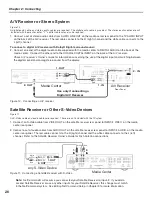
Connect the supplied Digital A/V cable from the MonitorLink
™
A/V Output on the media center rear panel to the
MonitorLink
™
A/V Input on the display left rear panel. You can secure in place the two cables just connected by
routing them through the cable clip mounted next to the AC power input on the back of the display.
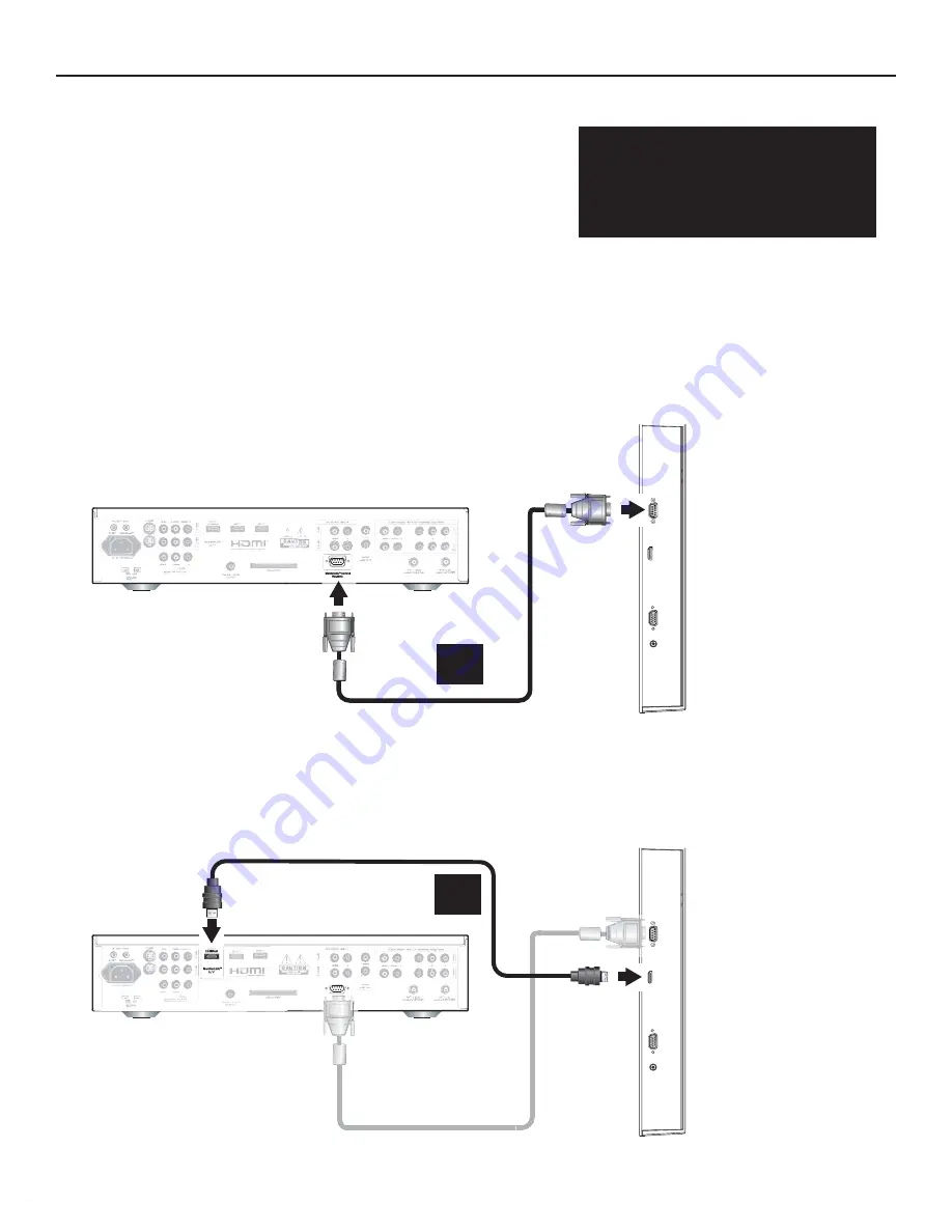
Figure 1. Connecting MonitorLink™ RS-232C Control cable
from Media Center to Display
-EDIA#ENTER
,EFT2EAR0ANEL
OF$ISPLAY
-ONITOR,INK
4-
!6)NPUT
-ONITOR,INK
4-
!6/UTPUT
#
Essential MonitorLink™ Connections
MonitorLink™ RS-232C Control and Digital A/V
Figure 1. MonitorLink™ RS-232C Control cable (required and provided)
Figure 2. MonitorLink™ Digital A/V cable (required and provided)
The media center is designed specifically to work with the LT-3280 and LT-3780 displays. The MonitorLink™ RS-232C
control connection allows the media center to turn the display and media center automatically on or off and control
A/V devices connected to the media center. The MonitorLink™ Digital A/V cable carries video and audio signals from
connected devices to the display.
A.
Connect the MonitorLink
™
Control cable from the MonitorLink Control terminal on the media center rear panel to
the MonitorLink™ Control terminal on the display left rear panel (MonitorLink is also called MonLink or M-Link).
Finger-tighten the retaining screws to ensure snug connections.
Figure 2. Connecting MonlitorLink™ Digital A/V
cable from Media Center to Display.
To operate as a complete HDTV,
the display must be connected
to the media center using both
required MonitorLink™ cables.
See the instructions below.


