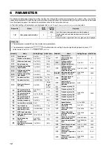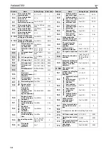
1
1 INSTALLATION OF THE INVERTER AND INSTRUCTIONS
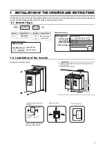
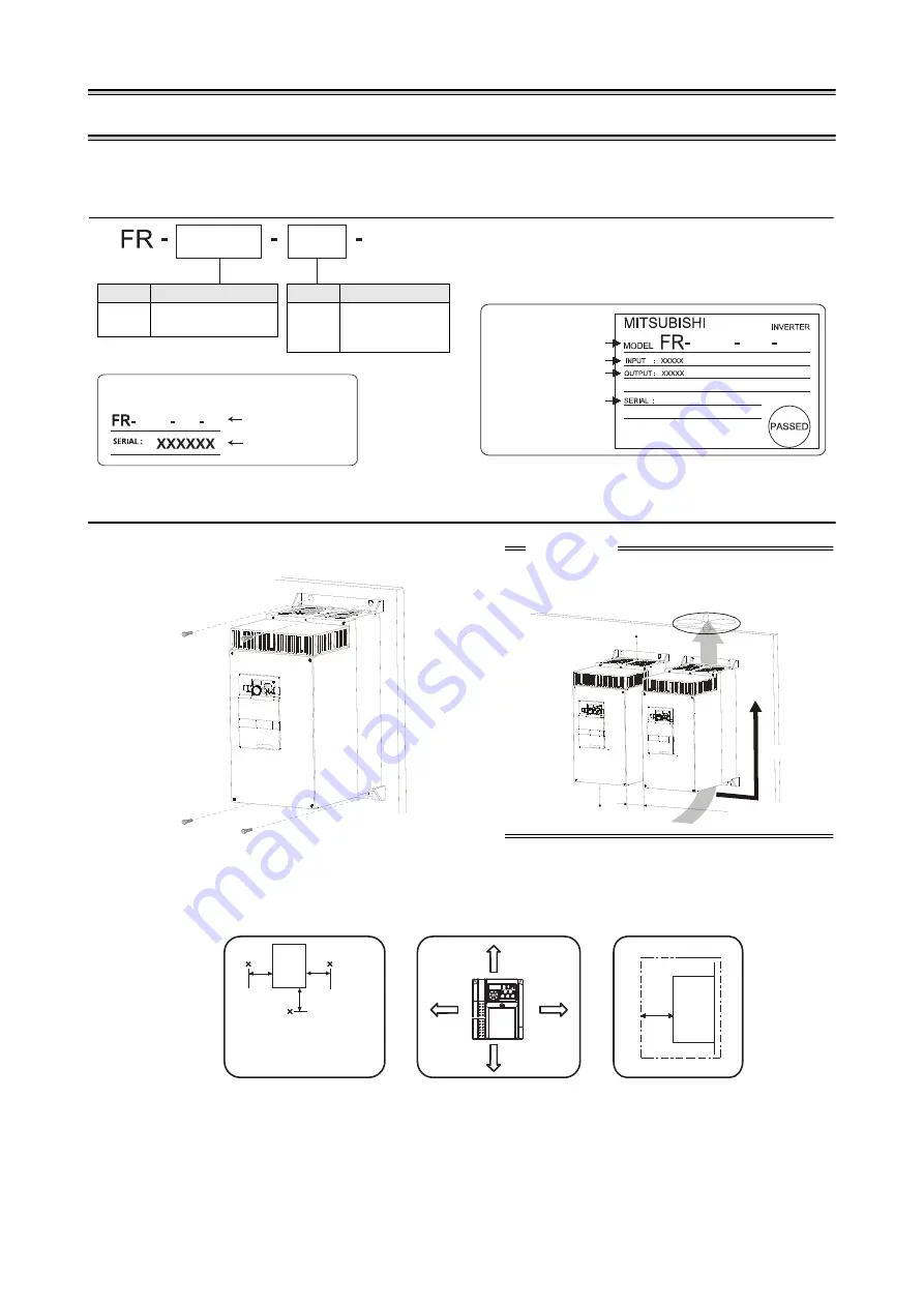
Unpack the inverter and check the capacity plate on the front cover and the rating plate on the inverter side face to
ensure that the product agrees with your order and the inverter is intact.
1.2 Installation of the inverter
Enclosure surface mounting
5.5
5.5
5.5
A741
A741
A741
K
K
K
1.1 Inverter Type
Symbol
Voltage Class
A741
Three-phase
400V class
Symbol
Type number
5.5
to
55
Indicate inverter
capacity [kW]
Capacity plate example
Rating plate example
Capacity plate
Rating plate
Serial number
Inverter type
Inverter type
Input rating
Output rating
Serial number
CAUTION
When encasing multiple inverters, install them in parallel as a
cooling measure.
Install the inverter vertically.
vertical
Refer to the clearances be
low.
Ambient air temperature and
humidity
Clearances (side)
5cm
5cm
5cm
Inverter
Measurement
position
Temperature:
−
10°C to +50°C
Humidity:
max. 90%
≥
5cm
Leave enough clearances
and take cooling measures.
Clearances (front)
≥
5cm
≥
10cm
≥
10cm
Inverter
≥
5cm
Measurement
position

