


156
2. Ethernet Communication
2.12 PROFINET
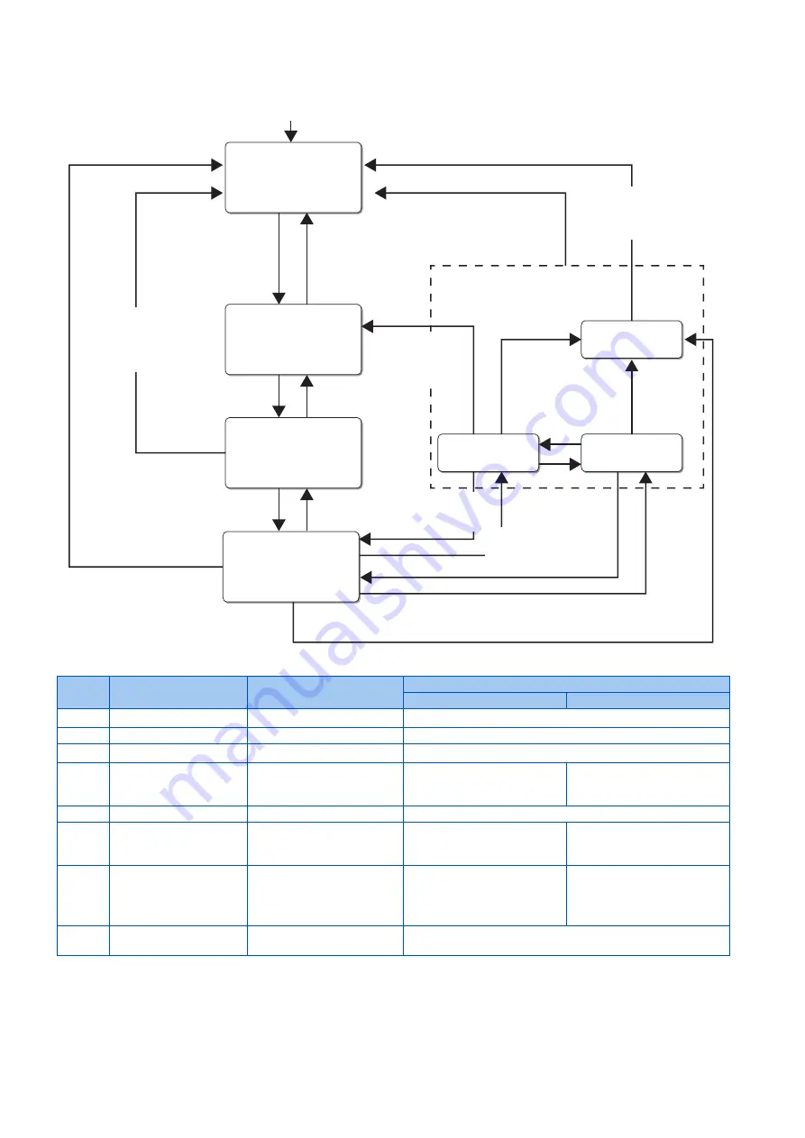
State transition diagram of the inverter
• Definition
*1
The inverter state is forcefully changed to S1 when an inverter fault occurs or in the operation mode other than Network operation mode.
*2
During position control, the servo ON/OFF status is switched along with state transition. The LX signal input using Inverter Control Parameters
(P20488 and P20489) (
) is disabled.
*3
When the output is shut off by the MRS signal or other signal, the RY signal remains OFF.
*4
For details of
Pr.1103
and
Pr.815
, refer to the Instruction Manual (Function).
S1: Switching On Inhibited
(ZSW1 bit 6 = true
bit 0, 1, 2 = false)
S2: Ready For Switching On
ZSW1
bit 0 = true
bit 1, 2, 6 = false
S3: Switched On
ZSW1
bit 0, 1 = true
bit 2, 6 = false
S4: Operation
ZSW1
bit 0, 1, 2 = true
bit 6 = false
OFF and
No Coast Stop and
No Quick Stop
(STW1 bit 0 = false and
bit 1 = true and
bit 2 = true)
Coast Stop or
Quick Stop
(STW1 bit 1 = false or
bit 2 = false)
ON
(STW1 bit 0 = true)
OFF
(STW1 bit 0 = false)
Enable Operation
(STW1 bit 3 = true)
Disable Operation
(STW1 bit 3 = false)
Coast Stop
(STW1 bit 1 = false)
Power supply ON
Coast Stop or
Quick Stop
(STW1 bit 1 = false or
bit 2 = false)
S5-1: ramp stop
S5-2: quick stop
S5-3: fault stop
ON
(STW1 bit 0
= true)
OFF
(STW1 bit 0
= false)
S5: Switching Off
(ZSW1 bit 0, 1 = true
bit 2, 6 = false)
Coast Stop
(STW1 bit 1 = false)
Standstill detected or
Disable Operation
(STW1 bit 3 = false)
Quick Stop
(STW1 bit 2 = false)
Quick Stop
(STW1 bit 2 = false)
Standstill detected or
Disable Operation
(STW1 bit 3 = false)
ON
(STW1 bit 0
= true)
OFF
(STW1 bit 0
= false)
(0)
(1)
(6)
(2)
(5)
(3)
(4)
(8)
(7)
(11)
(12)
(20)
(10)
(16)
(17)
(13)
(9)
(19)
(18)
(14)
(15)
Symbol
Name
Description
Inverter operation
Other than position control
Position control
S1
Switching On Inhibited
During stop (initial status)
Output shutoff (RY signal OFF)
S2
Ready For Switching On
During stop (ready)
Output shutoff (RY signal OFF)
S3
Switched On
During stop (standby)
Output shutoff canceled (RY signal ON)
S4
Operation
During operation (enabled)
Start command ON (rotation
direction depends on STW1 and
NSOLL_A settings)
Servo-ON status
S5
Switching Off
Deceleration stop
—
S5-1
ramp stop
Normal deceleration stop
Start command OFF, normal
deceleration stop
Servo-OFF status
Start command OFF, output
shutoff
S5-2
quick stop
Emergency stop
Start command OFF,
deceleration stop according to
the
Pr.1103
and
Pr.815
settings
Servo-OFF status
Start command OFF, output
shutoff
S5-3
fault stop
Deceleration stop due to a
communication error
Deceleration stop due to a communication error (
Pr.502
= "1 or 2")
Summary of Contents for E820S
Page 5: ...4 ...
Page 177: ...176 2 Ethernet Communication 2 15 Ethernet communication parameters MEMO ...
Page 207: ...206 3 RS 485 Communication 3 5 MODBUS RTU MEMO ...
Page 211: ...210 4 Other Communication Options 4 2 Automatic connection with GOT MEMO ...
Page 212: ...211 CHAPTER 5 CHAPTER 5 4 5 6 7 8 9 10 Common Settings ...
Page 219: ...218 5 Common Settings MEMO ...
Page 220: ...219 CHAPTER 6 CHAPTER 6 4 5 6 7 8 9 10 Appendix 6 1 How to check specification changes 220 ...


