


6
en
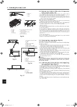
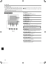
4.4. Indoor unit (Fig. 4-3)
Heat insulation for refrigerant pipes:
1 Wrap the enclosed large-sized pipe cover around the gas pipe, making sure that
the end of the pipe cover touches the side of the unit.
2 Wrap the enclosed small-sized pipe cover around the liquid pipe, making sure
that the end of the pipe cover touches the side of the unit.
3 Secure both ends of each pipe cover with the enclosed bands. (Attach the bands
20 mm from the ends of the pipe cover.)
• After connecting the refrigerant piping to the indoor unit, be sure to test the pipe
connections for gas leakage with nitrogen gas. (Check that there is no refrigerant
leakage from the refrigerant piping to the indoor unit.)
4. Refrigerant pipe and drain pipe
A
D
E
C
B
F
B
,
C
F
G
H
I
J
A
Refrigerant pipe and heat
insulation
B
Pipe cover (large)
C
Pipe cover (small)
D
Refrigerant pipe (gas)
E
Refrigerant pipe (liquid)
F
Band (large)
G
Cross-sectional view of
connection
H
Pipe
I
Heat insulation
J
Squeeze
Fig. 4-3
B
C
6
30 30
7
7
18
A
A
H
H
G
G
D E
C K
F
F
C
J
I
1
A
B
K
B
F
D
F
F
H
I
G
E
D
D
L
M
C
F
J
2
3
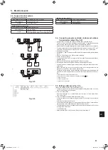
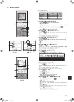
4.5. Drainage piping work (Fig. 4-4)
• The indoor parts of the drain pipe should be wrapped with polyethylene foam
insulation materials (specific gravity of 0.03, thickness of 9 mm or more).
• Use VP25 (O.D. ø32 PVC TUBE) for drain piping and provide 1/100 or more
downward slope.
• Be sure to connect the piping joints using a PVC type adhesive.
• Observe the figure for piping work.
• Use the included drain hose to change the extraction direction.
• When performing the drainage piping work, be sure to use the support metal hold-
ers.
If a load is applied to the drain socket that damages the hose or causes the hose
to become detached, water leakage may result.
1
Correct piping
G
Make the piping size large for grouped pip
-
ing.
2
Wrong piping
3
Grouped piping
H
Downward slope (1/100 or more)
A
Insulation (9 mm or more)
I
O.D. ø38 PVC TUBE for grouped piping
(9 mm or more insulation)
B
Downward slope (1/100 or more)
C
Support metal
J
Up to 85 cm
D
O.D. ø32 PVC TUBE
K
Air bleeder
E
Make it as large as possible
(about 10 cm)
L
Raised
M
Odor trap
F
Main unit
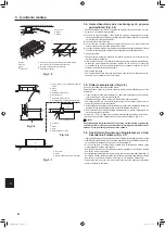
1. Connect the drain socket (supplied with the unit) to the drain port. (Fig. 4-5)
(Fix the tube using PVC adhesive then secure it with a band.)
2. Install a locally purchased drain pipe (PVC pipe, O.D. ø32).
(Fix the pipe using PVC adhesive then secure it with a band.)
3. Check that drain flows smoothly.
4. Insulate the drain port and socket with insulating material, then secure the material
with a band. (Both insulating material and band are supplied with the unit.)
5. Insulate the tube and pipe. (PVC pipe, O.D. ø32)
A
Main unit
G
Drain pipe (O.D. ø32 PVC TUBE)
B
Insulating material
H
Insulating material (purchased locally)
C
Band (large)
I
Transparent PVC pipe
D
Drain port (transparent)
J
O.D. ø32 PVC TUBE (Slope 1/100 or more)
E
Insertion margin
K
Drain socket
F
Matching
Fig. 4-4
Fig. 4-5
Max. 20 m
Max. 15 cm
1.5 - 2 m
(mm)
RG79F456H01_en.indd 6
2019/07/03 14:25:27
008
008