background image

13

tr

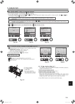
6.3.  Tahliye kontrolü (Fig. 6-7)

•  Suyun düzgün bir şekilde dışarı atıldığından ve bağlantı noktalarından herhangi bir 

su sızıntısı olmadığından emin olun.

Elektrik işleri tamamlandığı zaman.

. Soğutma çalıştırması sırasında su döküp kontrol edin.

Elektrik işleri tamamlanmadığı zaman.

. Acil durum çalıştırması sırasında su döküp kontrol edin.

*  Elektrik branşı kutusundaki kumanda panosu üzerinde bulunan bağlantı (SWE) 

ON  (AÇIK)  durumuna  getirildikten  sonra,  tek  fazlı  220-240V  klemenste  L  ve  N 

pozisyonuna getirilince, tahliye tepsisi ve fan aynı anda devreye sokulur.

Çalışma bittikten sonra bunu eski durumuna getirmeyi unutmayın.

6.  Çalışma testi

Fig. 6-7

A


Su besleme pompası

B


Su (yaklaşık 1000cc)

C


Tahliye tapası

D


Suyu çıkışın içine dökün

·  Suyu tahliye pompası mekanizma

-

sına kaçırmamaya özen gösterin.

Adım 2  Testi çalıştırın, hava akımı sıcaklığını ve otomatik kanadı kontrol edin.

1


F1

 düğmesine basarak, “Cool” (Soğutma) ve “Heat” (Isıtma) çalışma modları 

arasında geçiş yapın. (Fig. 6-5)

  Soğutma modu: Soğuk hava üflemesini kontrol edin.

  Isıtma modu: Sıcak hava üflemesini kontrol edin.

  * Dış ünite fanının çalışmasını kontrol edin.

2

  Kanatçık ayar ekranını açmak için   düğmesine basın.

OTOMATİK kanatçık kontrolü

1


F1


F2

 düğmeleri ile otomatik kanatçığı kontrol edin. (Fig. 6-6)

2


 düğmesine basarak “Test run” (Test çalıştırma) işlem ekranına dönün.

3


 düğmesine basın.

Adım 1  Uzaktan kumandayı “Test run” (Test çalıştırma) moduna alın.

1

  Ana menüden “Service” (Servis) öğesini seçin ve 

 düğmesine basın. 

2

  Servis menüsü seçildiğinde, bir pencere açılarak parola isteyecektir. (Fig. 6-2)

  Mevcut bakım parolasını (4 rakam) girmek için, 

F1

 veya 

F2

 düğmesi ile imleci değiştirmek istediğiniz haneye getirin ve her sayıyı (0’dan 9’a kadar) 

F3

 veya 

F4

 düğ

-

mesi ile değiştirin. Ardından, 

 düğmesine basın. 


Not:  İlk bakım parolası “9999”dur. İzinsiz girişi önlemek için varsayılan parolayı gerektiğinde değiştirin. Parolayı kullanacak 

kişilere bildirin.


Not:  Eğer bakım parolanızı unutursanız, bakım parolası ayar ekranından 

F1

 ve 

F2

 düğmelerine aynı anda üç saniye basılı tutarak parolanızı varsayılan parola 

olan “9999” değerine getirebilirsiniz.

3


F1

 veya 

F2

 düğmesi ile “Test run” (Test çalıştırma) öğesini seçin ve 

 düğmesine basın. (Fig. 6-3)

4


F1

 veya 

F2

 düğmesi ile “Test run” (Test çalıştırma) öğesini seçin ve 

 düğmesine basın. (Fig. 6-4)

B

A

C

D

F1

F2

F3

F4

Test run

Input maintenance info.

Settings

Check

Others

Main menu:

Service menu

Cursor

Test run menu

Cursor

Service menu:

Test run

Drain pump test run

F1

F2

F3

F4

Fig. 6-4

Service menu

Cursor

Select:

Enter maintenance password

F1

F2

F3

F4

Fig. 6-3

Fig. 6-2

Cool

Pipe

Auto

Switch disp.

Mode

Fan

Remain

Test run

F1

F2

F3

F4

Fig. 6-5

Remain

Vane

F1

F2

F3

F4

Fig. 6-6

RG79F456H01_tr.indd   13

2019/7/5   10:33:34

031

031

Summary of Contents for CITY MULTI PLFY-M-VEM Series

Page 1: ...nı monte etmeden önce bu kılavuzu ve dış ünite montaj kılavuzunu tamamıyla okuyun Türkçe For use with the R32 R410A R32 R410A ile beraber kullanmak için FOR INSTALLER INSTALLATION MANUAL For safe and correct use read this manual and the outdoor unit installation manual thoroughly before installing the air conditioner unit English RG79F456H01_cover1 indd 1 2019 05 23 19 17 39 001 001 ...

Page 2: ...потім мову bg Посетете горепосочения уебсайт за да изтеглите ръководства като изберете име на модел и след това език pl Odwiedź powyższą stronę internetową aby pobrać instrukcje wybierz nazwę modelu a następnie język cs Příručky naleznete ke stažení na internetové stránce zmíněné výše poté co zvolíte model a jazyk sk Na webovej stránke vyššie si môžete stiahnuť návody Vyberte názov modelu a zvoľte...

Page 3: ...ade securely with no tension applied on the terminal connections Also never splice the cables for wiring unless otherwise indicated in this document Failure to observe these instructions may result in overheating or a fire Do not use intermediate connection of the electric wires When installing or relocating or servicing the air conditioner use only the specified refrigerant written on outdoor uni...

Page 4: ...ightened too much the flare nut can break after an extended period If the unit is run for long hours when the air above the ceiling is at high temperature high humidity dew point above 26 ºC dew condensation may be produced in the indoor unit or the ceiling materials When operating the units in this condition add insulation material 10 20 mm to the entire sur face of the unit and ceiling materials...

Page 5: ...258 100 125 281 298 3 3 Branch duct hole and fresh air intake hole Fig 3 3 At the time of installation use the duct holes cut out located at the positions shown in Fig 3 3 as and when required A fresh air intake hole for the optional multi function casement can also be made Note The figure marked with in the drawing represent the dimensions of the main unit excluding those of the optional multi fu...

Page 6: ... Gauge D Ceiling opening dimensions Fig 3 5 Fig 3 6 Fig 3 7 3 5 Unit suspension procedures Fig 3 5 Suspend the main unit as shown in the diagram Figures given in parentheses represent the dimensions in case of installing optional multi function casement 1 In advance set the parts onto the suspension bolts in the order of the washers with insulation washers without insulation and nuts double Fit th...

Page 7: ...ly thin layer of refrigerant oil to pipe and joint seating surface before tightening flare nut Use two wrenches to tighten piping connections Use refrigerant piping insulation provided to insulate indoor unit connections Insulate carefully After connecting the refrigerant piping to the indoor unit be sure to test the pipe connections for gas leakage with nitrogen gas Check that there is no refrige...

Page 8: ...ing a PVC type adhesive Observe the figure for piping work Use the included drain hose to change the extraction direction When performing the drainage piping work be sure to use the support metal hold ers If a load is applied to the drain socket that damages the hose or causes the hose to become detached water leakage may result 1 Correct piping G Make the piping size large for grouped pip ing 2 W...

Page 9: ... to 100 mm A Electrical wiring service panel B Screw C Electrical box cover D Temporary hook for electrical box cover E Screw F Slide direction of the electrical box cover G Entry for power cable H Secure with the cable strap I Earth cable J Power terminal K Entry for wired remote controller and indoor outdoor connection cable L Drain Pan M Length of the cable not covered by the indoor outdoor con...

Page 10: ...del C Multiple of tripping current at tripping time 0 01 s Please pick up C from the tripping characteristic of the breaker Example of F2 calculation Condition PLFY VEM 4 PEFY VMA 1 V1 of PLFY VEM 19 8 V1 of PEFY VMA 38 C 8 refer to right sample chart F2 19 8 4 8 38 1 8 14 65 16 A breaker Tripping current 8 16 A at 0 01 s 3 Current sensitivity is calculated using the following formula G1 V2 Quanti...

Page 11: ... Remote controller Connect the 1 and 2 on indoor unit TB15 to a MAremote controller Non polarized 2 wire DC 9 to 13 V between 1 and 2 MA remote controller 2 M NET Remote controller Connect the M1 and M2 on indoor unit TB5 to a M NET remote controller Non polarized 2 wire DC 24 to 30 V between M1 and M2 M NET remote controller 3 Wireless remote controller When installing wireless signal receiver Co...

Page 12: ... Standard High ceiling SW21 1 SW21 2 SW21 1 SW21 2 SW21 1 SW21 2 SW21 1 SW21 2 SW21 1 SW21 2 SW21 1 SW21 2 OFF ON OFF OFF ON OFF OFF ON OFF OFF ON OFF 4 direction SW21 3 OFF 2 5 m 2 7 m 3 5 m 2 7 m 3 2 m 4 5 m SW21 4 ON 3 direction SW21 3 OFF 2 7 m 3 0 m 3 5 m 3 0 m 3 6 m 4 5 m SW21 4 OFF 2 direction SW21 3 ON 3 0 m 3 3 m 3 5 m 3 3 m 4 0 m 4 5 m SW21 4 OFF Note Make sure the SW21 switch are set ot...

Page 13: ...ches between and The AUTO mode operates as the usual automatic mode The AUTO mode operates using dual set points 5 9 5 Changing the pair No Fig 5 8 D Press the button 4 Each time the button 4 is pressed the pair No 0 3 changes Pair No of wireless remote controller Indoor PC board SW22 SW22 3 SW22 4 0 ON ON Initial setting 1 OFF ON 2 ON OFF 3 OFF OFF 5 9 6 Changing the backlight setting E Press the...

Page 14: ...eration mode Main menu Press to move the cursor down 8 Function button F2 Main display Press to decrease temperature Main menu Press to move the cursor up 9 Function button F3 Main display Press to increase temperature Main menu Press to go to the previous page 0 Function button F4 Main display Press to change the fan speed Main menu Press to go to the next page Controller interface Fig 6 1 Do not...

Page 15: ...B Water about 1000cc C Drain plug D Pour water through outlet Be careful not to spray water into the drain pump mechanism Step 1 Switch the remote controller to Test run 1 Select Service from the Main menu and press the button 2 When the Service menu is selected a window will appear asking for the password Fig 6 2 To enter the current maintenance password 4 numerical digits move the cursor to the ...

Page 16: ...ke grille from the grille as indicated by the arrows 2 7 2 2 Removing the corner panel Fig 7 4 Loose the 4 screws on the corner Slide the corner panel in the direction of the arrow 1 in the figure and remove the corner panel Fig 7 3 Fig 7 4 A Intake grille B Grille 1 C Intake grille levers D Grille hook E Hole for the grille s hook F Corner panel G Screw H Detail 7 3 Selection of air outlets For t...

Page 17: ...stalling signal receiver Fig 7 9 Route the lead wire white 9 poles for signal receiver corner panel from the side of the electrical box on the main unit Make sure to connect to CN90 white on the controller board Make sure that the lead wire of the signal receiver corner panel is passed through the claw of bellmouth The remaining lead wire must be held together without slack using a clamp into the ...

Page 18: ...to install the intake grille and the corner panel The direction of the intake grille can be changed according to the wishes of the customer A Screw 4 16 B Corner panel C Safety strap D Hook E Refrigerant pipe F Drain pipe G Company logo Installation in any position is possible H Initial position of the levers on the intake grille Although the clips can be installed in any of 4 positions the config...

Page 19: ...çalışan cihazları elektrikli ısıtıcıları ve diğer olası yangın kay naklarını alev alma kaynakları montaj onarım ve klimadaki diğer işlerin yapılacağı yerlerden uzak tutun Soğutucu madde alev ile temas ederse zehirli gazlar ortaya çıkar Kullanım sırasında soğutucu kaçağı meydana gelirse odayı havalandırın Soğutucunun alevle temas etmesi durumunda zehirli gazlar oluflabilir Bütün elektrik işleri ruh...

Page 20: ...unda geçme somun bir süre sonra kırılabilir Ünite tavanın üzerindeki hava yüksek sıcaklık yüksek nemde 26ºC üzeri çiylenme noktası iken çok uzun bir süre çalışırsa iç ünitede veya tavan malzemelerinde çiylenme nedeniyle yoğuşma oluşabilir Üniteler bu koşulda çalıştığında çiylenme nedeniyle yoğuşmayı önlemek için ünitenin tüm yüze yinde veya tavan malzemelerinde yalıtım malzemesi 10 20 mm kullanın ...

Page 21: ... temiz hava giriş deliği Fig 3 3 Montaj esnasında Şekil 3 3 te gösterilen konumlardaki kesilerek çıkarılmış hava deliklerini gerektiği zaman ve gerektiği şekilde kullanın Seçimlik çok işlevli kasa için de bir temiz hava giriş deliği açılabilir Not Resimdeki ile işaretli rakam seçimlik çok işlevli kasanınkiler dışında ana ünitenin boyutlarını temsil etmektedir Seçimlik çok işlevli kasayı monte eder...

Page 22: ...ini önlemek için koruyucu örtü olarak da kullanılabilir Takma işleminin ayrıntıları için montaj şablonuyla birlikte sağlanan talimatlara bakınız ambalajın üzerinde 3 4 Asma düzeninin yapısı asılacağı yerin yapısını güçlendiriniz Fig 3 4 Tavanda yapılacak işler binanın yapısına göre değişir Bunun ayrıntıları için inşa atçılara ve iç mimarlara danışılmalıdır 1 Tavanın ne ölçüde açılacağı Tavan tamam...

Page 23: ... boru ve conta bağlantı yüzeylerine ince bir tabaka halinde soğutucu yağı uygulayınız Boru bağlantılarını iki somun anahtarıyla sıkınız Soğutucu boru yalıtımında yalnızca iç ünite bağlantılarının yalıtımı için verilen yalıtım malzemelerini kullanın Dikkatli izole edin Soğutucu borusunu iç üniteye bağladıktan sonra boru bağlantılarında kaçak olup olmadığını azot gazıyla muhakkak test edin Soğutucu ...

Page 24: ...un zarar görmesine veya hortumun yerinden çıkmasına sebep olabilecek güç uygulandığında su sızıntısı meydana gelebilir 1 Doğru boru tesisatı G Gruplandırılmış tesisat için büyük çaplı boru kullanınız 2 Yanlış boru tesisatı 3 Gruplandırılmış tesisat H Aşağıya doğru meyil 1 100 veya daha fazla A İzolasyon 9 mm veya daha fazla I Gruplandırılmış tesisat için O D ø38 PVC boru 9 mm veya daha fazla izola...

Page 25: ...an kablo bırakın yakl 50 ila 100 mm A Elektrik kablosu servis paneli B Vida C Elektrik kutusu kapağı D Elektrik kutusu kapağı için geçici kanca E Vida F Elektrik kutusu kapağının kaydırma yönü G Güç kablosu girişi H Kablo teli ile sabitleyin I Toprak kablosu J Güç terminali K Kablolu uzaktan kumanda ve iç dış bağlantı kablosu için giriş L Tahliye Kabı M İç dış bağlantı kablosunun kılıfı tarafından...

Page 26: ...şul PLFY VEM 4 PEFY VMA 1 PLFY VEM V2 2 4 PEFY VMA V2 1 6 Kablo kalınlığı ve uzunluğu 1 5 mm2 0 2 km G1 2 4 4 1 6 1 48 0 2 20 8 Sonuç olarak akım hassasiyeti 30 mA 0 1 saniye veya daha azdır G1 Akım hassasiyeti 30 veya daha az 30 mA 0 1sn veya daha az 100 veya daha az 100 mA 0 1sn veya daha az V1 V2 PLFY VEM 19 8 2 4 1 2 3 4 6 8 10 20 C 6000 600 60 10 1 0 1 0 01 ÖRNEK Örnek şema Atma Süresi sn Nom...

Page 27: ...kan kumanda panosundaki CN90 a bağlayın İkiden fazla ünite kablosuz uzaktan kumanda kullanılarak grup kontrolünde çalış tırıldığı zaman TB15 i bunların her birine aynı numarayla bağlayın Pair Çift No ayarını değiştirmek için lütfen kablosuz uzaktan kumanda ile birlikte verilen kılavuza bakın İç ünitenin ve kablosuz uzaktan kumandanın varsayılan ayarına göre Pair Çift Numarası 0 dır A İç iletim kab...

Page 28: ... A PLFY M20VEM 220 240V 50Hz 220V 60Hz Maks 264V Min 198V 0 28 0 05 0 22 PLFY M25VEM 0 28 0 05 0 22 PLFY M32VEM 0 28 0 05 0 22 PLFY M40VEM 0 36 0 05 0 29 PLFY M50VEM 0 36 0 05 0 29 PLFY M63VEM 0 45 0 05 0 36 PLFY M80VEM 0 64 0 05 0 51 PLFY M100VEM 1 25 0 12 1 00 PLFY M125VEM 1 34 0 12 1 07 Not SW21 anahtarının ayarlandığından emin olun aksi takdirde sıcak soğuk ala mama gibi problemler oluşabilir ...

Page 29: ...AUTO OTOMATİK mod normal otomatik mod gibi çalışır AUTO OTOMATİK mod çift ayar noktalarını kullanarak çalışır 5 9 5 Çift No sunun değiştirilmesi Fig 5 8 D düğmesine 4 basın düğmesine 4 her basıldığında Çift No 0 3 değişecektir Kablosuz uzak tan kumandanın Çift No su İç PC kartı SW22 SW22 3 SW22 4 0 ON AÇIK ON AÇIK Başlangıç ayarı 1 OFF KAPALI ON AÇIK 2 ON AÇIK OFF KAPALI 3 OFF KAPALI OFF KAPALI 5 ...

Page 30: ... söner 7 İşlev düğmesi F1 Ana ekran Çalışma modunu değiştirmek için basın Ana menü İmleci aşağı hareket ettirmek için basın 8 İşlev düğmesi F2 Ana ekran Sıcaklığı azaltmak için basın Ana menü İmleci yukarı hareket ettirmek için basın 9 İşlev düğmesi F3 Ana ekran Sıcaklığı artırmak için basın Ana menü Önceki sayfaya gitmek için basın 0 İşlev düğmesi F4 Ana ekran Fan hızını değiştirmek için basın An...

Page 31: ...in Fig 6 6 2 düğmesine basarak Test run Test çalıştırma işlem ekranına dönün 3 düğmesine basın Adım 1 Uzaktan kumandayı Test run Test çalıştırma moduna alın 1 Ana menüden Service Servis öğesini seçin ve düğmesine basın 2 Servis menüsü seçildiğinde bir pencere açılarak parola isteyecektir Fig 6 2 Mevcut bakım parolasını 4 rakam girmek için F1 veya F2 düğmesi ile imleci değiştirmek istediğiniz haney...

Page 32: ...len şekilde ızgaradan ayırın 7 2 2 Köşe panelinin çıkarılması Fig 7 4 Köşede bulunan 4 vidayı gevşetin Köşe panelini çıkarmak için köşe panelini şekil deki 1 numaralı okla gösterilen şekilde itin Fig 7 3 Fig 7 4 A Hava giriş ızgarası B Izgara 1 C Hava giriş ızgarası kolları D Izgara kancası E Izgara kancasının deliği F Köşe paneli G Vida H Detay 7 3 Hava çıkışlarının seçilmesi Bu ızgara için boşal...

Page 33: ...kat edin Sinyal alıcısı köşe panelini panele takın ve vidayla sabitleyin Sinyal alıcısı köşe paneli ana ünitenin drenaj borusu tarafına takılamaz Fig 7 11 e bakın A Sinyal alıcısı köşe paneli B Izgara deliği Kablo ucunu geçirin C Çan ağzı tırnağı D Kablo E Kelepçe F Kablo bandı Kablo ucunu sabitleyin G Kontrol kartında CN90 H Vida 7 4 6 i see sensor köşe panelinin takılması Fig 7 10 Kablo ucunu el...

Page 34: ...ı takma hazırlığı bölümünde anlatılan prosedürü tersten izleyin Giriş ızgarasının yönü müşterinin arzusuna uygun olarak değiştirilebilir A Vida 4 16 B Köşe paneli C Emniyet teli D Kanca E Soğutucu borusu F Drenaj borusu G Şirket logosu Herhangi bir konumda monte etmek mümkündür H Giriş ızgarasındaki kolların başlangıç konumu Kıskaçlar bu 4 konumdan herhangi birinde takılabilmesine rağmen burada gö...

Page 35: ...A4_white_tombo indd 1 2018 08 09 14 11 29 035 035 ...

Page 36: ...mber on this manual before handing it to the customer HEAD OFFICE TOKYO BUILDING 2 7 3 MARUNOUCHI CHIYODA KU TOKYO 100 8310 JAPAN This product is designed and intended for use in the residential commercial and light industrial environment RG79F456H01_cover4 indd 19 2019 05 23 19 18 18 036 036 ...

Reviews: