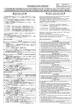
【立上げ・保守時の注意事項】
危 険
● 通電中に端子やコネクタに触れないでください。
感電の原因になります。
● 清掃は,必ずシステムで使用している外部供給電源を全相遮断してから
行ってください。全相遮断しないと,ユニットの故障や誤動作の原因に
なります。
注 意
● ユニットの分解,改造はしないでください。
故障,誤動作,ケガ,火災の原因になります。
● ユニットは落下させたり,強い衝撃を与えないでください。
ユニットの破損の原因になります。
● ユニットの盤への取付け・取外しは必ずシステムで使用している外部供
給電源を全相遮断してから行ってください。全相遮断しないと,ユニッ
トの故障や誤動作の原因になります。
● ユニットに触れる前には,必ず接地された金属などに触れて,人体など
に帯電している静電気を放電してください。
静電気を放電しないと,ユニットの故障や誤動作の原因になります。
【廃棄時の注意事項】
注 意
● 製品を廃棄するときは,産業廃棄物として扱ってください。
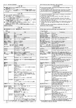
1. 仕様
項目
内容
入力点数
16点
絶縁方式
フォトカプラ絶縁
定格入力電圧
DC24V
定格入力電流
約5mA
使用電圧範囲
DC19.2~26.4V(リップル率5%以内)
最大同時入力点数
100%/62.5%(第2章参照)
ON電圧/ON電流
14V以上/3.5mA以上
OFF電圧/OFF電流
6V以下/1.7mA以下
入力抵抗
約4.7kΩ
OFF→ON 1.5ms以下(DC24V時)
応答時間
ON→OFF 1.5ms以下(DC24V時)
コモン方式
16点1コモン
(センサコネクタ(e-CON) 3線式)
入力形式
プラスコモン(シンクタイプ)
占有局数
1局32点割付け(16点使用)
電圧
DC20.4~26.4V(リップル率5%以内)
I/Oユニット
電源
電流
35mA以下(DC24V,全点ON時)
ノイズ耐量
DCタイプのノイズ電圧500Vp-p,ノイズ幅1μs,
ノイズ周波数25~60Hzのノイズシミュレータによ
る
耐電圧
DC外部端子一括-アース間AC500V 1分間
絶縁抵抗
DC外部端子一括-アース間DC500V絶縁抵抗計にて
10MΩ以上
保護等級
IP1XB
質量
0.10kg
外部接続
方式 *1
通信部
通信用ワンタッチコネクタ
[伝送回路]
(5ピン・圧接タイプ,コネクタ用プラグは別売:
A6CON-L5P)
〈オプション〉
通信用オンラインコネクタ:A6CON-LJ5P
電源部
電源・FG用ワンタッチコネクタ
[I/Oユニット電源,入力部外部供給電源・FG]
(5ピン・圧接タイプ,コネクタ用プラグは別売:
A6CON-PW5P,A6CON-PW5P-SOD)
〈オプション〉
電源用オンラインコネクタ:A6CON-PWJ5P
入出力部
センサコネクタ(e-CON)
[I/O信号]
(4ピン・圧接タイプ,コネクタ用プラグは別売)
適用DINレール
TH35-7.5Fe,TH35-7.5Al
(JIS C 2812に準拠)
通信用
コネクタ
適合ケーブル:FANC-110SBH,CS-110
電源・FG用
コネクタ
0.66~0.98mm
2
(AWG#18)
[φ2.2~3.0mm (A6CON-PW5P),
φ2.0~2.3mm (A6CON-PW5P-SOD)]
素線径0.16mm以上
絶縁被覆材質:PVC(耐熱ビニル)
適合電線
サイズ
入出力用
コネクタ
センサコネクタ(e-CON)
コネクタ用プラグは別売
(適合サイズ:0.08~0.5mm
2
,使用するコネクタ用
プラグにより異なる)
CC-Linkシステム小形タイプリモートI/Oユニット
ユーザーズマニュアル(詳細編)SH(名)3307参照
*1:各コネクタの圧着方法は,CC-Link システム小形タイプリモート I/O
ユニットユーザーズマニュアル(詳細編) SH(名)3307 を参照してくだ
さい。
【
STARTING AND MAINTENANCE PRECAUTIONS
】
DANGER
z
Do not touch terminals or connectors when the power is on. Doing so
could cause an electric shock.
z
Switch off all phases of the externally supplied power used in the system
when cleaning the module. Not doing so could result in electric shock.
CAUTION
z
Never try to disassemble or modify module. It may cause product failure,
malfunction, fire or cause injury.
z
Do not drop or apply any strong impact to the module. Doing so may
damage the module.
z
Completely turn off the externally supplied power used in the system
before mounting or removing the module to/from the panel. Not doing so
could result in damage to the product.
z
Always make sure to touch the grounded metal to discharge the electricity
charged in the electricity charged in the body, etc., before touching the
module.
Failure to do so may cause a failure or malfunctions of the module.
【
DISPOSAL PRECAUTIONS
】
CAUTION
z
When disposing of this product, treat it as industrial waste.
1. Specification
Item Description
Number of input points
16 points
Isolation method
Photocoupler
Rated input voltage
24 V DC
Rated input current
Approx. 5 mA
Operating voltage range
19.2 to 26.4 V DC (ripple ratio: within 5 %)
Max. simultaneous ON
input points
100 %/62.5 % (Refer to Chapter 2)
ON voltage/ON current
14 V or higher/3.5 mA or higher
OFF voltage/OFF current
6 V or lower/1.7 mA or lower
Input resistance
Approx. 4.7 k
Ω
OFF
→
ON
1.5 ms or lower (when 24 V DC)
Response
time
ON
→
OFF
1.5 ms or lower (when 24 V DC)
Wiring method for common 16 points/common
(Sensor connector (e-CON) 3-wire type)
Input form
Positive common (sink type)
Number of stations
occupied
1 station 32 points assignment (use 16 points)
Voltage
20.4 to 26.4 V DC (ripple ratio: within 5 %)
I/O module
power supply
Current
35 mA or lower (when 24 V DC, all points ON)
Noise durability
DC type noise voltage 500 Vp-p, noise width 1
µs, noise frequency 25 to 60 Hz (noise simulator
condition)
Withstand voltage
500 V AC for 1 minute between all DC external
terminals and ground
Insulation resistance
10 M
Ω
or higher, measured with a 500 V DC
insulation resistance tester between all DC
external terminals and ground
Protection of degree
IP1XB
Weight 0.10
kg
External
wiring
system *1
Communication
part
One-touch connector for communication
[Transmission circuit] (5 pins pressure welding
type) The plug for the connector is sold
separately: A6CON-L5P
< Option >
Online connector for communication:
A6CON-LJ5P
Power
supply
part
One-touch connector for power supply and FG
[I/O module power supply, External power supply
for input and FG] (5 pins pressure welding type)
The plug for the connector is sold separately:
A6CON-PW5P, A6CON-PW5P-SOD
< Option >
Online connector for power supply:
A6CON-PWJ5P
I/O part
Sensor connector (e-CON) [I/O signal]
(4 pins pressure welding type) The plug for the
connector is sold separately
Applicable DIN rail
TH35-7.5Fe, TH35-7.5Al
(conforming to IEC 60715)
Connector for
communication
Applicable cable: FANC-110SBH, CS-110
Connector for
power supply
and FG
0.66 to 0.98 mm
2
(18AWG)
[
φ
2.2 to 3.0 mm (A6CON-PW5P),
φ
2.0 to 2.3
mm (A6CON-PW5P-SOD)] wire diameter 0.16
mm or more
Outer insulation layer material: PVC
(Heat-resistant vinyl)
Applicable
wire size
Connector for
I/O
Sensor connector (e-CON)
Plug for connector sold separately
(Applicable wire size: 0.08 to 0.5 mm
2
,
depending on the plug for connector)
Refer to CC-Link System Compact Type Remote
I/O Module User’s Manual SH(NA)4007.
*1: For crimping each connector, refer to CC-Link System Compact Type Remote
I/O Module User’s Manual (SH(NA)4007).


