


E-32
The current value which is used as the reference of the load current indication LED varies depending on the
characteristics setting.
When the “OVER” LED is lighting, the current value
is over LTD pick-up current. The circuit breaker
carries out trip operation after specified time.
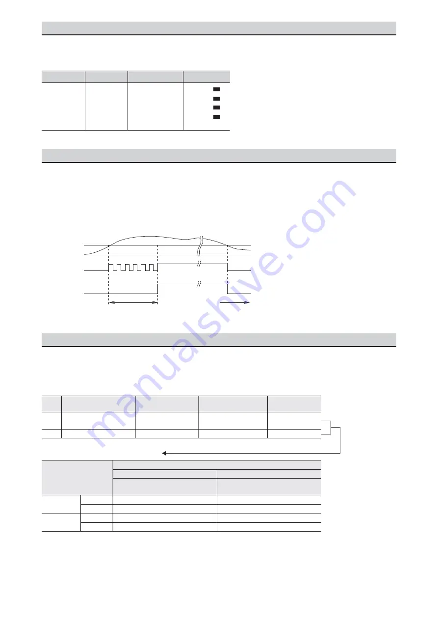
When the current exceeds the pre-alarm current setting (Ip), the PAL LED will blink. When the half time of LTD
time passes, the PAL LED will light and output the contact. For the operation time, refer to the characteristic curve.
When an ETR with DP is used and the load current exceeds the pre-alarm current setting (Ip), the back light
of the liquid crystal display (LCD) will change from white to red.
(The back light will only change to red. Pre-alarm information will not be displayed on the LCD.)
16.1 Load current LED
16.2 Pre-alarm function
16.3 Control power supply
It is necessary for trip indicator (LED, output contact) operation and current indication. For overcurrent and
short-circuit protection, even if there is no control power supply, the operation is done using the internal CT energy.
(Note) Taking into consideration the capacity of voltage drop due to factors other than the circuit breaker, set
the working voltage range of the power supply capacity.
OFF
Load current
Blink
Lighting
Current
1/2 T
L
ON
Ip
PAL LED
PAL contact
output
Elapsed time (t)
Usage
General
protection use
S1
Iu
Uninterrupted
current
%Iu
ETR type
Base current
LED indication
OVER
100
80
60
P3
P4
10
15
5 output contacts
5 output contacts
Type
Alarm output
Criterion for
power requirement (VA)
Applicable voltage
range (V)
85-264 AC
85-138 DC
18-72 DC
Rated voltage
100-240 AC (50/60 Hz)/
100-125 DC
24-60 DC
AC
(50/60 Hz)
DC
240
0.5
0.05
1
1
1
1
0.1
1
Power supply module
Contact capacity (Type P3 and P4)
Voltage (V)
Resistive load
Inductive load
cos
φ
= 0.4
L/R = 0.7
cos
φ
= 1.0
Current (A)
120
125
30


