5
SERVICE MODE
1. OVERVIEW
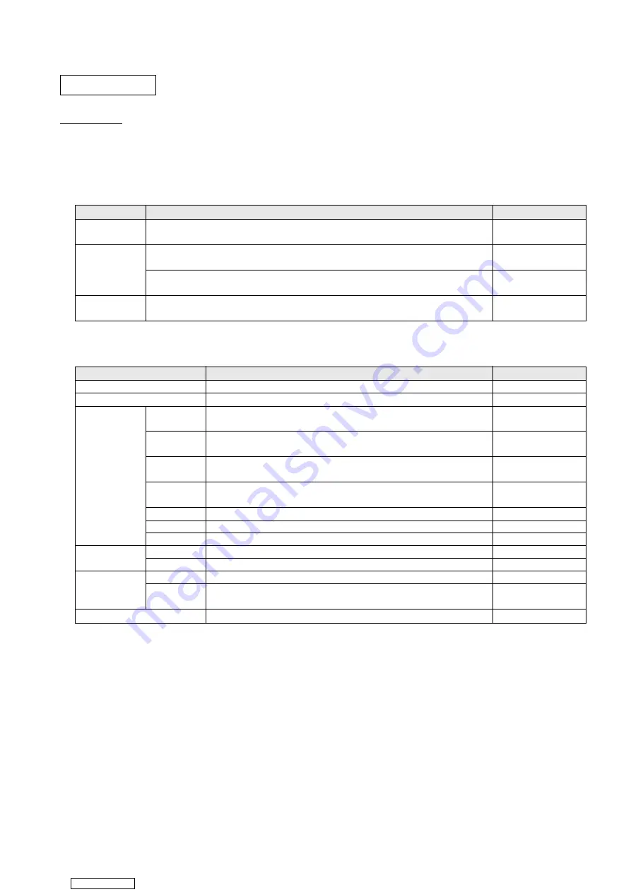
Table 1-1 shows an overview of the service mode.
In the service mode, the screen is always ON regardless of opening/closing state.
Item
Condition
Remarks
Service mode
configuration
As shown in Table 1-2.
Within 5 seconds after power-on (ACC OFF -> ON), perform the following operation.
Infrared remote control
[RTN] -> [SOURCE] -> [MENU] -> [SETUP] -> [CURSOR] -> [DISP]
Panel button.
Entry method
Within 5 seconds after power-on (ACC OFF -> ON), perform the following operation.
Transition to the hard-
Turn ILL off and on 8 times.
ware check screen.
Termination
method
Turn off the power (ACC OFF) or use SERVICE MENU to select EXIT.
Table 1-1 Service mode outline
Screen
Overview
Remarks
SERVICE MENU
Provides service mode items to be selected.
See Figure 2-1.
AUTO
Automatic check mode
Displays a color bar pattern by OSD.
COLOR BAR
Designed for color purity check.
See Figure 3-1.
Displays a white image by OSD.
WHITE
Designed for block spot check.
See Figure 3-2.
Displays a black image by OSD.
SCREEN
BLACK
Designed for bright spot check.
See Figure 3-2.
CHECK
Displays a flicker check image by OSD.
FLICKER
Designed for flicker check.
See Figure 3-3.
RED
Displays a red image by OSD.
See Figure 3-2.
GREEN
Displays a green image by OSD.
See Figure 3-2.
BLUE
Displays a blue image by OSD.
See Figure 3-2.
HARDWARE
HARDWARE
Displays hardware check results.
See Figure 4-1.
CHECK
PANEL KEY
Designed for operation panel button check.
See Figure 4-2.
SYSTEM
Displays information on software version, region setting, etc.
See Figure 5-1.
SYSTEM
Displays connection information on M-BUS adaptor, serial communication,
CHECK
CONNECTION
etc.
See Figure 5-2.
INITIALIZE
Initializes the settings to the defaults.
See Figure 6-1.
Table 1-2 Service mode configuration
Downloaded from


