background image

8

GB

D

F

I

NL

E

SW

P

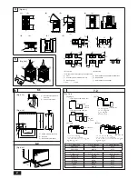
4. Space required around unit

[Fig. 4.0.1] (P.2)

<A> Top view

<B> Side view

<C> When there is little space up to an obstruction

A

Front

B

No restrictions on wall height (left and right)

C

Air outlet guide (Procured at the site)

D

Must be open

E

Wall height (H)

F

No restrictions on wall height

L

1

: 450

L

2

: 250

(1) Basic space required

A space of at least 250 mm is necessary at the back for inlet air. Taking servicing,
etc. from the rear into account, a space of about 450 mm should be provided, the
same as at the front.

(2) When there is an obstruction above the unit

(3) When inlet air enters from right and left sides of unit

Wall heights (H) of the front and the back sides shall be within overall height of
unit.

When the total height is exceeded, add the “h” dimension of the 

Fig. 4.0.1

 to L

1

and L

2

.

(4) When unit is surrounded by walls

Note:

Wall heights (H) of the front and the back sides shall be within overall
height of unit.

If the panel height is exceeded, add the “h” dimension of the Fig. 4.0.1 to
L

1

 and L

2

.

L

1

: 450

L

2

: 250

Example:

When h is 100,
the L

1

 dimension becomes 450 + 100 = 550 mm.

(5) Collective installation and continuous installation

Space required for collective installation and continuous installation:
When installing several units, leave the space between each block considering
passage for air and people.

Open in the two directions.

In case wall height (H) exceeds overall height of unit, add “h” dimension (h =
wall height <H> – overall height of unit) to * marked dimension.

If there is a wall at both the front and the rear of the unit, install up to four units
consecutively in the side direction and provide a space of 1000 mm or more as
inlet space/passage space for each four units.

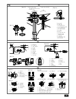
5. Lifting method and weight of product

[Fig. 5.0.1] (P.2)

 Caution:

Be very careful to carry product.

- Do not have only one person to carry product if it is more than 20 kg.
- PP bands are used to pack some products. Do not use them as a mean for transportation because they are dangerous.
- Do not touch heat exchanger fins with your bare hands. Otherwise you may get a cut in your hands.
- Tear plastic packaging bag and scrap it so that children cannot play with it. Otherwise plastic packaging bag may suffocate children to death.
- When carrying in outdoor unit, be sure to support it at four points. Carrying in and lifting with 3-point support may make outdoor unit unstable, resulting in a fall of it.

6. Installation of unit

6.1. Installation

[Fig. 6.1.1] (P.2)

A

M10 anchor bolt procured at the site.

B

Corner is not seated.

Fix unit tightly with bolts so that unit will not fall down due to earthquake or
gust.

Use concrete or angle for foundation of unit.

Vibration may be transmitted to the installation section and noise and vibration
may be generated from the floor and walls, depending on the installation con-
ditions. Therefore, provide ample vibrationproofing (cushion pads, cushion
frame, etc.).

Be sure that the corners are firmly seated. If the corners are not firmly seated,
the installation feet may be bent.

 Warning:

Be sure to install unit in a place strong enough to withstand its weight.
Any lack of strength may cause unit to fall down, resulting in a personal
injury.

Have installation work in order to protect against a strong wind and earth-
quake.

Any installation deficiency may cause unit to fall down, resulting in a
personal injury.

When building the foundation, give full attention to the floor strength, drain water
disposal <during operation, drain water flows out of the unit>, and piping and wir-
ing routes.

Down piping and down wiring precautions

When down piping and down wiring are performed, be sure that foundation and
base work does not block the base through holes. When down piping is performed,
make the foundation at least 100 mm high so that the piping can pass under the
bottom of the unit.

[Fig. 6.1.2]


(P.2)

A

Bottom piping through hole

B

(bolt hole)

C

(bolt hole for old models)

6.2. Connecting direction for refrigerant pip-

ing

[Fig. 6.2.1]


(P.2)

7. Refrigerant piping installation

Flare connection must be applied to the indoor unit and liquid piping of the outdoor
unit, whilst flange connection must be applied to the gas piping of the outdoor unit.
For the branching, brazing connection must be applied.

 Warning:

Always use extreme care to prevent the refrigerant gas (R407C) from leaking
while using fire or flame. If the refrigerant gas comes in contact with the
flame from any source, such as a gas stove, it breaks down and generates a
poisonous gas which can cause gas poisoning. Never weld in an unventilated
room. Always conduct an inspection for gas leakage after installation of the
refrigerant piping has been completed.

7.1. Caution

1

Use the following materials for refrigeration piping.

Material: Use refrigerant piping made of phosphorus deoxidized copper. In
addition, be sure that the inner and outer surfaces of the pipes are clean
and free of hazardous sulphur, oxides, dust/dirt, shaving particles, oils,
moisture, or any other contaminant.

2

Commercially available piping often contains dust and other materials.  Always
blow it clean with a dry inert gas.

3

Use care to prevent dust, water or other contaminants from entering the piping
during installation.

4

Reduce the number of bending portions as much as possible, and make bend-
ing radius as big as possible.

5

Always observe the restrictions on the refrigerant piping (such as rated length,
the difference between high/low pressures, and piping diameter).  Failure to do
so can result in equipment failure or a decline in heating/cooling performance.

Summary of Contents for 250MYA

Page 1: ... uso seguro y correcto lea detalladamente este manual de instalación antes de montar la unidad de aire acondicionado MANUALE DI INSTALLAZIONE Per un uso sicuro e corretto leggere attentamente questo manuale di installazione prima di installare il condizionatore d aria INSTALLATIEHANDLEIDING Voor een veilig en juist gebruik moet u deze installatiehandleiding grondig doorlezen voordat u de aircondit...

Page 2: ...red at the site D Must be open E Wall height H F No restrictions on wall height L1 450 L2 250 PUH P200 250 7 7 2 H L H L L PUH P200 250 L 50 m H 40 m L Ra Rb 70 m L Ra L Rb 50 m Ra Rb 8 m H 40 m h 1 m 1 Single 2 Twin H h L R a R b PUH P200 250 Fig 7 2 1 A mm Å Outdoor unit ı Gas pipe size Ç Liquid pipe size PUH P200 ø25 4 ø12 7 PUH P250 ø28 58 ø12 7 B mm Î Indoor unit ı Gas pipe size Ç Liquid pipe...

Page 3: ...ly open state A Nitrogen gas B To indoor unit C System analyzer D Lo Knob E Hi Knob F Stop valve G Liquid pipe H Gas pipe I Outdoor unit J Service port B Ball valve liquid side Fig 8 4 4 Fig 8 4 3 Fig 8 4 2 C A B D E Fig 8 4 1 B A D C E E E D A B D F G B D Floor fireproofing E I B C Outer wall exposed A B A Inner wall concealed A B D C B Outer wall F H D B G E Roof pipe shaft I A J 1m 1m F Penetra...

Page 4: ...ecting with PEH P400 500 2 With heater B C D PUH P200 250 E E A B C A B C A A B C PUH P200 250 F 0 D A B C PEH P400 500 PUH P200 250 F 1 3 Grouping 16 outdoor units A D E E E E PUH P200 250 F 0 PUH P200 250 F 14 PUH P200 250 F 15 L1 L2 L3 N S1 S2 S3 S1S2 S3 L1 L2 L3 N S1 S2 S3 S1S2 S3 L1 L2 L3 N S1 S2 S3 S1S2 S3 S1S2 S3 B C A B C B C A 5 Grouping 16 outdoor units Connecting with PEH P400 500 A B C...

Page 5: ...N 1 2 3 4 5 6 7 OFF ON 1 2 3 4 5 6 8 OFF ON 1 2 3 4 5 6 9 OFF ON 1 2 3 4 5 6 10 OFF ON 1 2 3 4 5 6 11 OFF ON 1 2 3 4 5 6 12 OFF ON 1 2 3 4 5 6 13 OFF ON 1 2 3 4 5 6 14 OFF ON 1 2 3 4 5 6 15 ø40 ø27 ø27 ø34 ø34 ø38 1 C A B D Fig 9 4 1 9 4 A When installing conduct from bottom panel B When installing conduct from front panel C Mounting plate attached D Knock out hole 9 ...

Page 6: ...t the safety limit from being exceeded If the refrigerant leak and cause the safety limit to be exceeded hazards due to lack of oxygen in the room could result When moving and reinstalling the air conditioner consult the dealer or an authorized technician If the air conditioner is installed improperly water leakage electric shock or fire may result After completing installation work make sure that...

Page 7: ...ombine indoor units within the capacity of the outdoor unit Use ester oil ether oil or alkylbenzene small amount as the refrigerator oil to coat flares and flange connections The refrigerator oil will degrade if it is mixed with a large amount of mineral oil Use liquid refrigerant to fill the system If gas refrigerant is used to seal the system the composition of the refriger ant in the cylinder w...

Page 8: ...transmitted to the installation section and noise and vibration may be generated from the floor and walls depending on the installation con ditions Therefore provide ample vibrationproofing cushion pads cushion frame etc Be sure that the corners are firmly seated If the corners are not firmly seated the installation feet may be bent Warning Be sure to install unit in a place strong enough to withs...

Page 9: ...ing with PEH P400 500 Î Indoor unit 2 Twin 3 Triple 4 Four Caution Total bends are 15 units and max bends are 8 units within L R R R R Ra L R R R R Rb L R R R R Rc and L R R R R Rd 25 25 25 25 50 50 33 33 33 25 25 50 20 40 40 Model Additional refrigerant charge 8 Additional refrigerant charge 8 1 Additional refrigerant charge L Main section actual length Ra Rb Rc Rd Join section actual length The ...

Page 10: ...ncrease Turn the flare nut beyond this point by the angle shown in the table above Caution Always remove the connecting pipe from the ball valve and braze it out side the unit Brazing the connecting pipe while it is installed will heat the ball valve and cause trouble or gas leakage The piping etc inside the unit may also be burned Use ester oil ether oil or alkylbenzene small amount as the refrig...

Page 11: ... and connect it correctly Secure it so that the cable applies no external pressure to the terminal connection If the connection is faulty or the cable is not fully secured overheating or fire could result Caution Depending on the location of the unit a current leakage breaker may be required If a current leakage breaker is not installed electric shock could result Do not use breakers or fuses with...

Page 12: ...e operation mode is to be changed first stop it using SW 4 1 then after chang ing the operation mode start the test run again using SW 4 1 If the 2 hour timer is set the test run will stop automatically after 2 hours During the test run the room temperature display on the indoor unit will indi cate the temperature of the indoor unit piping When you operate the test run from OC1 all trial runs are ...

Page 13: ...h on the outdoor unit board the segments light up to indicate the running condition of the unit and the particulars of the check code SW2 setting 123456 000000 011110 010110 110110 011100 111100 Item Operation mode relay output Outdoor unit control condition Indoor unit control condition IC1 IC2 Indoor unit control condition IC3 IC4 Error code history 1 Error code history 2 Display contents tens p...

Page 14: ...he basis of time or piping temperature During defrosting the fan will stop When the supplementary electric heater is ON the fan will run for 1 minute after opera tion stops in order to expel excess hot air during heating only After the switch is turned to ON or until the piping temperature reaches 35 C there will be 5 minutes of light air operation After that there will be 2 minutes of low air ope...

Page 15: ... The product at hand is based on the following EU regulations Low Voltage Directive 73 23 EEC Electromagnetic Compatibility Directive 89 336 EEC This product is designed and intended for use in the residential commer cial and light industrial environment HEAD OFFICE MITSUBISHI DENKI BLDG 2 2 3 MARUNOUCHI CHIYODA KU TOKYO 100 8310 JAPAN ...

Reviews: