background image

4

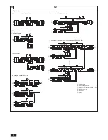
L1 L2 L3 N S1 S2 S3 OUT

L1 L2 L3 N S1 S2 S3

S1 S2 S3 S1 S2 S3 L1 L2 L3 N

OUT IN IN

OUT OUT IN IN

L1 L2 L3 N

L1 L2 L3 N

L1 L2 L3 N S1 S2 S3

S1 S2 S3

S1 S2 S3

L1 L2 L3 N S1 S2 S3

S1 S2 S3

S1 S2 S3

9

9.2

A

 Power supply

B

 Earth leakage breaker

C

 Wiring circuit breaker or isolating switch

D

 Remote controller

E

 Indoor unit

F

 Address

PEH-RP200, 250

[Fig. 9.2.1]

L1 L2 L3 N

L1 L2 L3 N

S1 S2 S3

S1 S2 S3

(1) Connecting with PEH-RP200, 250

A

B C

C

D

PUH-P200, 250

A

B

(2)  Free multi - component system

Without heater

A

B C

D

E

E

PUH-P200, 250

(4)  Connecting with PEH-P400, 500

With heater

B C

D

PUH-P200, 250

E

E

A

B

C

A

B

C

A

A

B C

PUH-P200, 250

F

 (0)

D

A

B C

PEH-P400, 500

PUH-P200, 250

F

 (1)

(3)  Grouping (16 outdoor units)

A

D

E

E

E

E

PUH-P200, 250

F

(0)

PUH-P200, 250

F

(14)

PUH-P200, 250

F

(15)

L1 L2 L3 N S1 S2 S3

S1 S2 S3

L1 L2 L3 N S1 S2 S3

S1 S2 S3

L1 L2 L3 N S1 S2 S3

S1 S2 S3

S1 S2 S3

··

·

··

B C

A

B C

B C

A

(5)  Grouping (16 outdoor units) [Connecting with PEH-P400, 500]

A

B

C

L1 L2 L3 N S1 S2 S3

L1 L2 L3 N S1 S2 S3

L1 L2 L3 N S1 S2 S3

L1 L2 L3 N S1 S2 S3

S1 S2 S3 S1 S2 S3 L1 L2 L3 N

S1 S2 S3 S1 S2 S3 L1 L2 L3 N

OUT OUT IN IN

OUT OUT IN IN

OUT OUT IN IN

OUT OUT IN IN

A

B C

A

B C

PUH-P200, 250

F

 (0)

PUH-P200, 250

F

 (1)

PEH-P400, 500

D

A

B

C

PUH-P200, 250

F

 (14)

PUH-P200, 250

F

 (15)

PEH-P400, 500

A

B C

A

B C

A

B

C

Summary of Contents for 250MYA

Page 1: ... uso seguro y correcto lea detalladamente este manual de instalación antes de montar la unidad de aire acondicionado MANUALE DI INSTALLAZIONE Per un uso sicuro e corretto leggere attentamente questo manuale di installazione prima di installare il condizionatore d aria INSTALLATIEHANDLEIDING Voor een veilig en juist gebruik moet u deze installatiehandleiding grondig doorlezen voordat u de aircondit...

Page 2: ...red at the site D Must be open E Wall height H F No restrictions on wall height L1 450 L2 250 PUH P200 250 7 7 2 H L H L L PUH P200 250 L 50 m H 40 m L Ra Rb 70 m L Ra L Rb 50 m Ra Rb 8 m H 40 m h 1 m 1 Single 2 Twin H h L R a R b PUH P200 250 Fig 7 2 1 A mm Å Outdoor unit ı Gas pipe size Ç Liquid pipe size PUH P200 ø25 4 ø12 7 PUH P250 ø28 58 ø12 7 B mm Î Indoor unit ı Gas pipe size Ç Liquid pipe...

Page 3: ...ly open state A Nitrogen gas B To indoor unit C System analyzer D Lo Knob E Hi Knob F Stop valve G Liquid pipe H Gas pipe I Outdoor unit J Service port B Ball valve liquid side Fig 8 4 4 Fig 8 4 3 Fig 8 4 2 C A B D E Fig 8 4 1 B A D C E E E D A B D F G B D Floor fireproofing E I B C Outer wall exposed A B A Inner wall concealed A B D C B Outer wall F H D B G E Roof pipe shaft I A J 1m 1m F Penetra...

Page 4: ...ecting with PEH P400 500 2 With heater B C D PUH P200 250 E E A B C A B C A A B C PUH P200 250 F 0 D A B C PEH P400 500 PUH P200 250 F 1 3 Grouping 16 outdoor units A D E E E E PUH P200 250 F 0 PUH P200 250 F 14 PUH P200 250 F 15 L1 L2 L3 N S1 S2 S3 S1S2 S3 L1 L2 L3 N S1 S2 S3 S1S2 S3 L1 L2 L3 N S1 S2 S3 S1S2 S3 S1S2 S3 B C A B C B C A 5 Grouping 16 outdoor units Connecting with PEH P400 500 A B C...

Page 5: ...N 1 2 3 4 5 6 7 OFF ON 1 2 3 4 5 6 8 OFF ON 1 2 3 4 5 6 9 OFF ON 1 2 3 4 5 6 10 OFF ON 1 2 3 4 5 6 11 OFF ON 1 2 3 4 5 6 12 OFF ON 1 2 3 4 5 6 13 OFF ON 1 2 3 4 5 6 14 OFF ON 1 2 3 4 5 6 15 ø40 ø27 ø27 ø34 ø34 ø38 1 C A B D Fig 9 4 1 9 4 A When installing conduct from bottom panel B When installing conduct from front panel C Mounting plate attached D Knock out hole 9 ...

Page 6: ...t the safety limit from being exceeded If the refrigerant leak and cause the safety limit to be exceeded hazards due to lack of oxygen in the room could result When moving and reinstalling the air conditioner consult the dealer or an authorized technician If the air conditioner is installed improperly water leakage electric shock or fire may result After completing installation work make sure that...

Page 7: ...ombine indoor units within the capacity of the outdoor unit Use ester oil ether oil or alkylbenzene small amount as the refrigerator oil to coat flares and flange connections The refrigerator oil will degrade if it is mixed with a large amount of mineral oil Use liquid refrigerant to fill the system If gas refrigerant is used to seal the system the composition of the refriger ant in the cylinder w...

Page 8: ...transmitted to the installation section and noise and vibration may be generated from the floor and walls depending on the installation con ditions Therefore provide ample vibrationproofing cushion pads cushion frame etc Be sure that the corners are firmly seated If the corners are not firmly seated the installation feet may be bent Warning Be sure to install unit in a place strong enough to withs...

Page 9: ...ing with PEH P400 500 Î Indoor unit 2 Twin 3 Triple 4 Four Caution Total bends are 15 units and max bends are 8 units within L R R R R Ra L R R R R Rb L R R R R Rc and L R R R R Rd 25 25 25 25 50 50 33 33 33 25 25 50 20 40 40 Model Additional refrigerant charge 8 Additional refrigerant charge 8 1 Additional refrigerant charge L Main section actual length Ra Rb Rc Rd Join section actual length The ...

Page 10: ...ncrease Turn the flare nut beyond this point by the angle shown in the table above Caution Always remove the connecting pipe from the ball valve and braze it out side the unit Brazing the connecting pipe while it is installed will heat the ball valve and cause trouble or gas leakage The piping etc inside the unit may also be burned Use ester oil ether oil or alkylbenzene small amount as the refrig...

Page 11: ... and connect it correctly Secure it so that the cable applies no external pressure to the terminal connection If the connection is faulty or the cable is not fully secured overheating or fire could result Caution Depending on the location of the unit a current leakage breaker may be required If a current leakage breaker is not installed electric shock could result Do not use breakers or fuses with...

Page 12: ...e operation mode is to be changed first stop it using SW 4 1 then after chang ing the operation mode start the test run again using SW 4 1 If the 2 hour timer is set the test run will stop automatically after 2 hours During the test run the room temperature display on the indoor unit will indi cate the temperature of the indoor unit piping When you operate the test run from OC1 all trial runs are ...

Page 13: ...h on the outdoor unit board the segments light up to indicate the running condition of the unit and the particulars of the check code SW2 setting 123456 000000 011110 010110 110110 011100 111100 Item Operation mode relay output Outdoor unit control condition Indoor unit control condition IC1 IC2 Indoor unit control condition IC3 IC4 Error code history 1 Error code history 2 Display contents tens p...

Page 14: ...he basis of time or piping temperature During defrosting the fan will stop When the supplementary electric heater is ON the fan will run for 1 minute after opera tion stops in order to expel excess hot air during heating only After the switch is turned to ON or until the piping temperature reaches 35 C there will be 5 minutes of light air operation After that there will be 2 minutes of low air ope...

Page 15: ... The product at hand is based on the following EU regulations Low Voltage Directive 73 23 EEC Electromagnetic Compatibility Directive 89 336 EEC This product is designed and intended for use in the residential commer cial and light industrial environment HEAD OFFICE MITSUBISHI DENKI BLDG 2 2 3 MARUNOUCHI CHIYODA KU TOKYO 100 8310 JAPAN ...

Reviews: