background image

MICRO 8 

Installation and user manual  

Page 13 of 24 

Introduction 


The MITECH antennas can be managed manually via the dip-switches on both the RX and 
TX modules or by using the MITECH Radar Barrier configuration proprietary program. 

IMPORTANT: the modules always keep the last saved configuration in memory even in 
the event of a power failure. 

Installation 

As standard the dip-switches on the RX and TX modules are programmed as follows: 


1. Position the CNF dip-switch of the RX and TX module in ON mode. In this condition the led will 

start to flash for a few seconds, confirming the input in configuration mode (on the TX module 
the red led will remain lit, see paragraph TX Module - setting the transmission level attenuation 
by 4dB on page ...). 


2. Defining the working frequency by programming the FREQ dip-switches of both modules,        

the programming of the dip-switches of the RX module must be the same as that of the TX 
module.

 If you do not want to change the frequency go directly to point 3. 


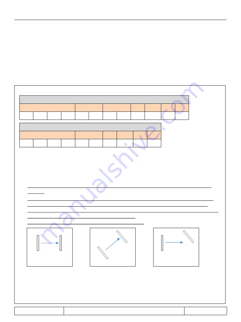
3. Orient the RX module towards the TX module in order to obtain the greater intensity of the 

green RX led and the greater speed of the buzzer signal (to activate the buzzer act on the 
BUZZER jumper). The turning on of the red led and the lower speed of the buzzer signal, mean 
that you are moving away from the optimal position.                                                                                                 
If necessary also act on the orientation of the TX module. 


4. At the end of the alignment if you want to keep the led on, program the led dip-switches in ON 

mode on both modules. 


5. If you do not want to change other parameters and then exit the configuration mode, program 

the CNF dip-switch in OFF mode on both modules, avoiding interrupting the signal and moving 
the antennas. 

RX MODULE 

FREQ 

SENS LEVEL 

SENS TIME 

ABS 

CNF 

S/A 

LED 

OFF 

OFF 

OFF 

OFF 

OFF 

OFF 

OFF 

OFF 

OFF 

OFF 

ON 

OFF 

TX MODULE 

FREQ 

SENS LEVEL 

ABS 

CNF 

S/A 

LED 

OFF 

OFF 

OFF 

OFF 

OFF 

OFF 

OFF 

OFF 

ON 

OFF 

Manual control 

Put in use 

TX 

RX 

RX 

TX 

TX 

RX 

YES 

YES 

NO 

Summary of Contents for MICRO 8

Page 1: ...MICRO 8 MINIATURIZED DIGITAL MICROWAVE BARRIER 200 m RANGE WITH PLANAR ANTENNA Installation and user manual MADE IN ITALY ...

Page 2: ...s 10 Receiver board RX 11 Description of dip switch and terminal board Transmitter board TX 12 Description of dip switch and terminal board Installation 13 Manual configuration by dip switch 13 RX module signal sensitivity setting RX module setting of the signal attenuation time TX module setting of 4dB transmission signal attenuation Control through software RS485 15 Description of columns and pa...

Page 3: ...ry derivation with ultra compact dimensions due to the absence of the cumbersome antenna dish The presence of an intruder is detected using a system of high frequency electromagnetic waves MICRO 8 is suitable for industrial residential and commercial areas prisons military settlements and in general in all applications where it is also necessary to protect large areas WARNINGS Use shielded cables ...

Page 4: ...ATE COVER MAIN SUPPORT BRACKET WITH CABLE PASSAGE PROTECTION ALSO USABLE WITH MICRO BOX AND MICRO PL ACCESSORIES COVER CAP SCREW TAMPER RX or TX ANTENNA RS485 MODULE WITH BUZZER BOX FOR WALL OR POLE MOUNTING CABLE GLAND MICRO BOX MICRO PL POLE MOUNTING BRACKET TO USE WITH MICRO BOX Dimensions 100x100x50 mm ...

Page 5: ...gures 3 and 4 the main structure where the RX or TX antenna is connected the serrated washer the M16 nut tightening it with a 16 mm wrench 5 Insert the cables and make the connections see pages 11 and 12 Note the tamper signal can be taken by connecting it directly to the microswitch or by connecting the microswitch to the TAMPER IN input of the antenna and then picking up the signal from the TAMP...

Page 6: ...sed make a hole in the base of the MICRO BOX verifying that the hole is in line with that of the wall cable outlet figure 1 If not make a hole in one of the four sides of the base and fix the PG8 figure 2 3 Drill a hole in the center of the MICRO BOX cover using the template provided figure 3 4 Insert the cables into the base and into the MICRO BOX cover into the main bracket and close using the f...

Page 7: ...h figure 2 4 Insert the following components figures 3 and 4 the main structure where the RX or TX antenna is connected the serrated washer the M16 nut tightening it with a 16 mm wrench 5 Insert the cables and make the connections see pages 11 and 12 Note the tamper signal can be taken by connecting it directly to the microswitch or by connecting the microswitch to the TAMPER IN input of the anten...

Page 8: ...t at the back of the pole and using the four M4x70 screws and the supplied washers fix the MICRO PL bracket to the base of the MICRO BOX figures 3 and 4 3 Drill a hole in the center of the MICRO BOX cover using the template provided figure 5 4 Insert the cables into the base and into the MICRO BOX cover into the main bracket and close using the four supplied screws figure 6 5 Follow the procedure ...

Page 9: ...USTMENT Vertical adjustment It is possible to orient the antenna vertically by adjusting the four fixing screws up to a maximum of 5 MICRO 8 Installation and user manual Page 9 of 24 FRONT VIEW SIDE VIEW 1 LATERAL VIEW 2 5 DOWNWARD ADJUSTMENT LATERAL VIEW 3 5 UPWARD ADJUSTMENT ...

Page 10: ...ing the ZR conformation and soil conditions Techinical features Maximum range 200 m Detection speed from 0 1 to 10 0 m s Power supply from 12 to 36 Vdc Consumption module TX 70 mA module RX 110 mA Recovery time after alarm notification 10 s Duration of the report 5 s Operating frequency from 24 000 to 24 250 GHz K band Selectable frequencies By dip switch 16 by software 250 Maximum lobe height 2 5...

Page 11: ... FREQ frequency setting SENS LEVEL signal attenuation level setting SENS TIME signal attenuation duration setting ABS detection mode setting PARAMETER NOT TO CHANGE CNF activation of configuration mode S A activation of the RS485 module for software management LED led activation Terminal board description TAMPER IN tamper input TAMPER OUT tamper output 0 A B RS485 ALARM alarm output WARN anti mask...

Page 12: ...p switch description FREQ frequency setting SENS LEVEL attenuation of the 4 dB transmission level ABS not used CNF activation of configuration mode S A activation of the RS485 module for software management LED led activation Terminal board description TAMPER IN tamper input TAMPER OUT tamper output 0 A B RS485 ALARM fault output WARN not used GND 0 V VIN 12 Vdc TERMINAL BLOCK DIP SWITCH MODULE RS...

Page 13: ...of the RX module must be the same as that of the TX module If you do not want to change the frequency go directly to point 3 3 Orient the RX module towards the TX module in order to obtain the greater intensity of the green RX led and the greater speed of the buzzer signal to activate the buzzer act on the BUZZER jumper The turning on of the red led and the lower speed of the buzzer signal mean th...

Page 14: ...e led to stop flashing 2 Program the two dip switches following the combinations indicated in the following table 3 Exit the configuration mode by programming the CNF dip switch in OFF mode avoiding interrupting the signal and moving the antenna RX board duration setting of signal attenuation DIP 1 DIP 2 OFF OFF 50 mS ON OFF 150 mS OFF ON 250 mS ON ON 350 mS TX board 4dB transmission level attenua...

Page 15: ...ion speed according to the converter model used standard 19200 bps Select the Open Port command wait a few seconds and then the SCAN key After about 16 seconds all the antennas connected to the serial port will be displayed see Figure 1 example of a pair of antennas connected to COM7 MIRS485 module MITECH radar barrier configuration program start Com Ports Baud rate Open Port SCAN Figure 1 The MIT...

Page 16: ...s you want to change TX or RX and click once figure 1 Wait for the control window to open figure 2 and enter a value between 0 and 249 and click OK figure 3 In this phase the new value set on the TX Freq and RX Freq cells will be displayed To save the modification click with the mouse on the red cell of the address you are configuring figure 4 TX LEVEL COLUMN Displays the 4dB attenuation of the tr...

Page 17: ...m signal To change this parameter place the mouse on the cell of the address you want to modify and click once figure 1 Wait for the control window to open figure 2 and enter a value between 20 and 350 then click OK figure 3 To save the modification click with the mouse on the red cell of the address you are configuring figure 4 COLUMN ALARM OFFSET Displays the level in dB of attenuation of the al...

Page 18: ...t detection mode This parameter cannot be changed Figure 1 Figure 2 Figure 3 READ WRITE REAL TIME COLUMNS READ COLUMN Reading enabling column for changes Instructions click with the mouse on the green box of the address you want to read modify WRITE COLUMN Column for writing editing parameters Instructions Once the changes have been made to an address click on the corresponding red box with the mo...

Page 19: ...E RS485 TERM IMPORTANT In the first and last modules connected insert the TERM jumper IMPORTANT Using an adapter with 120 Ohm fixed termination measurable value between pins A B insert the TERM jumper in the last connected module Using a terminated adapter selectable set the value of 120 Ohm and insert the TERM jumper in the last connected module Using an adapter without termination insert a resis...

Page 20: ... the snowpack or grass must not exceed the limit of 30 cm beyond which the device may not report any movement intrusion to its indoor 3 Avoid creating interference due to incorrect pointing of multiple TX antennas towards the same RX antenna 4 Use shielded cables 5 Supply the device with a stabilized voltage of 13 8 Vdc 6 Installation must be carried out by qualified personnel 7 MITECH is not resp...

Page 21: ...MICRO 8 Installation and user manual Page 21 of 24 Product photos 20 cm Ø 8 cm 110 cm ...

Page 22: ...MICRO 8 Installation and user manual Page 22 of 24 Notes ...

Page 23: ...MICRO 8 Installation and user manual Page 23 of 24 ...

Page 24: ...ction Via Ramazzone 23 43010 Fontevivo PR Italia Phone 39 02 48006383 Fax 39 02 48025620 tech mitech security com www mitech security com MADE IN ITALY MICRO 8 Rev 03 09 2019 MITECH srl reserves the right to change the information in this document without warning ...

Reviews: