


40
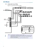
4.15.1 ALCN-792MISO DIP Switch Setting
Set the DIP switches on SW1 starting at address 1 for the first ALCN-792MISO adder and
consecutively up to seven for the next six ALCN-792MISO modules. Refer to Appendix C for
DIP switch settings.
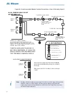
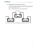
4.15.2 ALCN-792D Daughter Board Installation
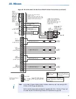
The location of Loop 1 and 2 terminals on ALCN-792D are shown in Figure 27 below. Also
shown are the jumper locations.
The ALCN-792D Daughter Board provides another two addressable loops when connected to
the ALCN-792MISO Quad Loop Adder Board. This daughter board is mounted over the ALCN-
792MISO using the four screws and spacers provided. Wire the two addressable loops on the
ALCN-792D Daughter Board in the same manner as the ALCN-792MISO addressable loops
are wired.
If the loops have shielding, connect the shields to the terminals marked COM(-). To prevent the
board reporting a ground fault, do not connect shields on SLC lines to earth ground.
Note: Unshielded wiring is preferred.
Figure 27 ALCN-792D Daughter Board
Notes for ALCN-792D:
• All circuits are power limited and must use type FPL, FPLR, or FPLP power limited
cable.
• Loop wiring: maximum loop resistance is 40 ohms total. These lines are power-limited
and fully supervised.
LOOP (3)
LOOP (4)
P1
To Main Board
Connector P6
Four mounting holes (mount to
ALCN-792MISO board with screws
and spacers provided)
Connect ribbon cable
from this board to the
ALCN-792MISO board P6
+
- + -
S S
+
- + -
B
A
A
B
COM (-)
JW2 - Normally set to
1-2, can be set to 2-3
to prevent noise from
CLIP System Sensor
sounder bases on
Loop 3
JW1 - Normally set to
1-2, can be set to 2-3
to prevent noise from
CLIP System Sensor
sounder bases on
Loop 4
SHIELD
i
Summary of Contents for FX-MNS-6000
Page 2: ......


