background image

3

Charging the battery

Make sure that the electrical information on the label of the charging unit 
corresponds to that of the power source.
Plug the power supply into an electrical outlet.
Plug the power supply jack into the socket on the back of the device.
Do not use the power supply if it is wet or damp.

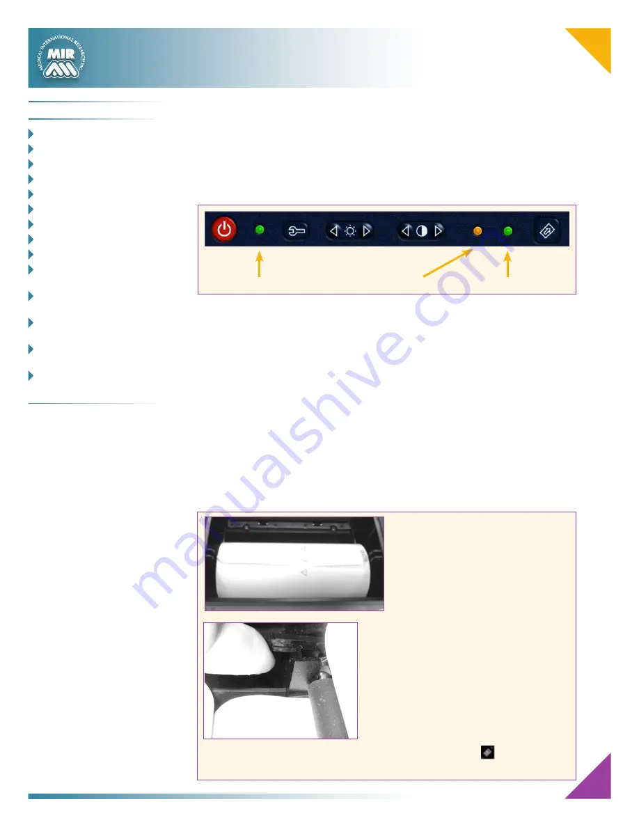
The charging process has several phrases which are indicated by two LEDs, green 
and orange (as shown above). 

•   Immediately after connecting the power supply, the orange LED starts  

to flash.

•  After a few seconds the orange LED stops flashing and remains lit.
•   For about 10 minutes the charging is partial while device automatically 

checks the battery condition.

•  After about 10 minutes the charging starts and proceeds to a full charge.
•   When charging is completed, the orange LED turns off and the green LED 

lights up.

Loading the thermal paper

Open the lid of the thermal paper compartment and remove it from the device; 
remove the paper roll holder. Insert the new roll of paper onto the paper roll holder.

Green LED 

Orange LED 

Green LED 

POWER ON 

Battery charging 

Battery charged

Guide to the correct positioning of the 
paper roll holder

Push the paper into the slot located under the 
traction reel (black rubber reel).
A sensor (as indicated in the image) detects 
the paper and automatically advances it.
This image shows the position of the paper in 
relation to the traction reel. The paper must 
advance through the slot in the compartment 
when it is closed; close the lid of the 
compartment.
If necessary make the paper advance 
manually by pressing the 

 button on the 

keyboard.

C

o n t e n t s


 o

VerVIew

 _________________ 1

 K

eyboard

 _________________ 2

 S

ymbolS


and

 I

con

S

 ________ 2


c

harging


the

 b

attery

 ___ 3

  l

Oading

 t

hermal

 P

aPer

 _ 3

 n

ew

 S

ubject

 d

ata

 e

ntry

 __ 4

 S

PIrometry

 FVc t

eSt

 ______ 5

 S

PIrometry

 Vc t

eSt

 ________ 5

 S

PIrometry

 mVV t

eSt

 _____ 5

  d

ata

 t

ranSmISSIon


VIa


  b

luetooth

 _______________ 6

  d

ata

 t

ranSmISSIon


VIa


  b

luetooth


For


PrIntIng

 __ 6

  c

onnectIon


to


a

 Pc 


VIa


a

 uSb 

Port

 __________ 7

  c

onnectIon


to


a

 Pc 


VIa


a

 rS 232 

Port

 _______ 7

  d

ownloadIng

 d

ata


From


  d

eVIce


to

 Pc __________8-9

Summary of Contents for Spirolab III

Page 1: ...ry FVc teSt ______5 SPIrometry Vc teSt________5 SPIrometry mVV teSt _____5 data tranSmISSIon VIa bluetooth_______________6 data tranSmISSIon VIa bluetooth For PrIntIng __6 connectIon to a Pc VIa a uSb...

Page 2: ..._______________1 Keyboard__________________2 Symbols and Icons_________2 Charging the Battery______3 Loading Thermal Paper____3 New Subject Data Entry___4 Spirometry FVC Test_______5 Spirometry VC Tes...

Page 3: ...w last test View bronchodilation tests Make POST test Make oximetry test Print Make FVC test Make VC test Make MVV test Number keys Specifies female sex Specifies male sex Confirm last operation This...

Page 4: ...ll holder Insert the new roll of paper onto the paper roll holder Green LED Orange LED Green LED POWER ON Battery charging Battery charged Guide to the correct positioning of the paper roll holder Pus...

Page 5: ...etric details of the same subject This avoids having to reinsert all of the data of that patient HEIGHT Enter the subject s height in cm or in inches according to the current configuration using the n...

Page 6: ...message VC IVC on the display will indicate that the ventilatory profile has been measured and you can now proceed to carry out the VC or IVC test VC test When the message VC IVC appears inspire slowl...

Page 7: ...ransfer test data directly to a printer with Bluetooth The sequence of activities to be followed is When the test is finished press twice spirolabIII will carry out the phases of connection At the end...

Page 8: ...tween the device and the PC ensure that the led on the device is on Connection to a PC through a RS 232 port SpirolabIII can be connected to a PC through a RS 232 serial port This leaves the USB port...

Page 9: ...completion of downloading the data from the device you will see in the table of temporary files received a log of the current download Then in the table below it will show all the tests that have not...

Page 10: ...button at the top of the screen and create a new patient After creating the patient continue the procedure as mentioned above Contents Overview__________________1 Keyboard__________________2 Symbols a...

Page 11: ......

Page 12: ......

Reviews: