background image

108

Data Processor

Functions

Displaying the Stored Data

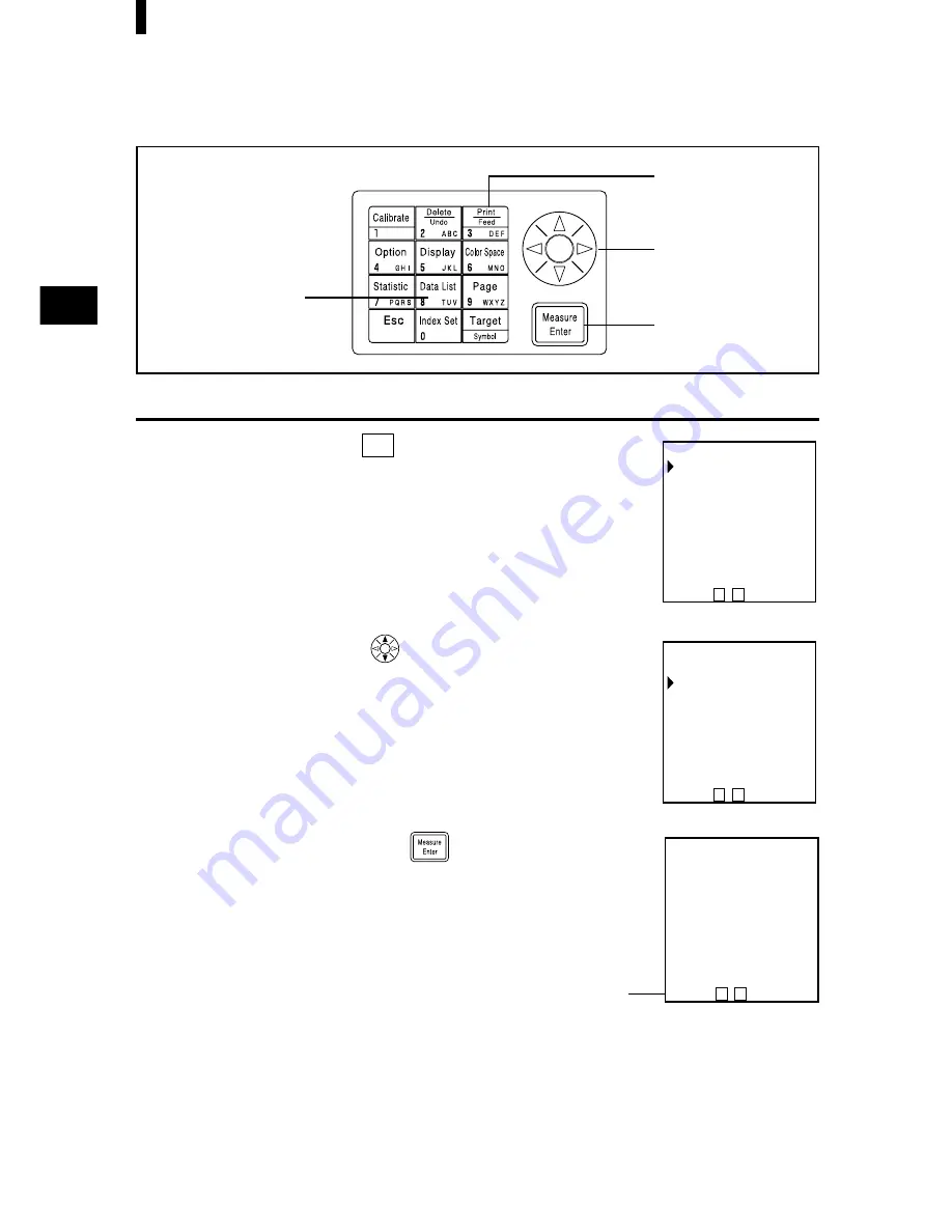
<Displaying Individual Data Sets>

[Operating Procedure]

1

Press the Data List key 

Data List

TUV

 while in the measurement

screen.

The data list screen appears.

2

Select a page using the 

 key.

3

Press the Measure/Enter key 

.

The measurement data screen of the selected page is displayed.
It is not possible to add (measure) new data here.

List screen

Measurement data

screen

Page number

[DATA LIST]  1/1 
 P02
 P01
 P00

P00   

C    P  

 [0030]

T00      [0010]
  L*=  74.72
  a*= +15.32   
  b*= +10.21  
 ΔL*=  +0.11 
 Δa*=  −0.01   
 Δb*=  +0.13   
 ΔE*=   0.18    

P01   

C    P  

 [0030]

[DATA LIST]  1/1 
 P02
 P01
 P00

P00   

C    P  

 [0030]

2,5

3,6

1

4

Summary of Contents for CR-400 -

Page 1: ...CHROMA METER CR 400 410 Instruction Manual Advanced Test Equipment Rentals www atecorp com 800 404 ATEC 2832 Established 1981...

Page 2: ...t the AC adapter from the AC outlet Denotes a prohibited operation Never disassemble the instrument Notes on This Manual Copying or reproduction of all or any part of the contents of this manual witho...

Page 3: ...e a fire and should be removed Do not connect or disconnect the AC adapter with wet hands Doing so may cause electric shock Take special care not to allow liquid or metal objects to enter the instrume...

Page 4: ...ether Introduction Thank you for buying a Minolta product This instrument is a high precision light weight Chroma Meter developed for Absolute Measurement and Difference Measurement in a wide range of...

Page 5: ...for operating pro cedure The Measuring Head has the key and the data processor has the key Their functions are followings Data Processor key moves cursor or scrolls screen left and right key moves cu...

Page 6: ...harge on or in the vicinity of CR 400 erroneous can occur In this cace please repeat the last mesurement If strong static electricity is received at the moment measurement is made the measurement valu...

Page 7: ...of the rated voltage and frequency Use an AC power source which is within 10 of the rated voltage and frequency Recommended Batteries A low ambient temperature will cause a drop in battery performanc...

Page 8: ...ing the white calibration plate close the cover and store it Do not throw away the packing materials cardboard box cushioning material plastic bags etc They can be used to protect the instrument durin...

Page 9: ...ead Key Panel 16 Data Processor 17 Data Processor Key Panel 18 Chapter 1 Measuring Head 1 This section describes use of the measuring head by itself Function guide 22 Preparation 23 Inserting the Batt...

Page 10: ...This section describes functions which run by setting the measuring head using the optional CR 400 utility software CR S4w or the Color data software ChromaMagic CR S3w although the head cannot be se...

Page 11: ...surements for automatic average 5 Illuminant 6 Back light 7 Buzzer 8 Displayed color limit 9 Remote mode Setting the Displayed Color Limit 74 CMC Parameter Setting 75 Initial Setting 76 Displaying Mea...

Page 12: ...User Index 127 Connecting to External Devices 128 Connecting the PC 128 SIP SOP Connections 129 Changing to Remote Mode 129 Applications 131 User Calibration Procedure Flow 131 User Calibration 132 W...

Page 13: ...rocessor Used to connect the measuring head to the data pro cessor for this instrument only 13 pin specification 1 3m long AC Adapter AC A17 Supplies power from an AC outlet to the instrument Input 12...

Page 14: ...cessor Hard Case CR A103 Used for storing measuring head data processor and accessories Do not use for transportation Glass Light Projection Tube CR A33a A33f for CR 400 Head CR A33e for CR 410 Head T...

Page 15: ...white and black CR 400 Utility Software CR S4w CD ROM This software uploads measurement data uploads and downloads of user index converts to Excel format and helps tweak and re use measurement data V...

Page 16: ...ze Battery x4 RS 232C Cable Head DP connection CR A101 White Calibration Plate CR A43 Glass Light Projection Tube CR A33a with convex glass Glass Light Projection Tube CR A33e Glass Light Projection T...

Page 17: ...s shown 6 Light projection tube The CR 400 light projection tube can be replaced with the optional CR A33a c d and f light projection tubes The CR 410 light projection tube can be replaced with the op...

Page 18: ...return to the measurement screen while in the menu screen Used to cancel operations while in the white calibration or color differ ence target color screens Returns to normal mode in the PC mode Disp...

Page 19: ...er This is where the roll paper thermal paper is stored 5 Printer Prints data on the roller paper thermal paper 6 LCD Displays measurement data and setting items 7 Display contrast Turning the dial ad...

Page 20: ...letes or undo a data displayed in the data list Deletes a page while data list is displayed in the page data list Deletes a color difference target color while a color difference target color list is...

Page 21: ...creen for editing the currently selected color difference target color Only when Measuring Head is connected 13 Cursor key Moves the cursor up down left and right Up down keys Adds 1 to the displayed...

Page 22: ...ers sp _ Numbers sp 3 Up Down key Changes input letter type Pressing the cursor key down upper case Latin letters numbers lower case Latin letters upper case Latin letters Pressing the cursor key up u...

Page 23: ...21 Chapter 1 Measuring Head 1 This chapter describes how to use the measuring head alone...

Page 24: ...difference display 30 Change display Absolute value display 54 Color difference display Pass Caution Fail display 55 Color space Color space selection 31 Color difference Color difference Target colo...

Page 25: ...the instrument for more than two weeks make sure that the batteries are removed If the batteries are left in the instrument for long periods of time battery electrolyte may leak and damage the instru...

Page 26: ...asuring head 2 Insert 4 AAA size batteries in accordance with the po larity indications shown in the battery chamber Notes on Use Do not touch the boot switch under any circumstances as this will eras...

Page 27: ...t Accumulated dirt or water on the prongs of the AC adapter s plug may cause a fire and should be removed Do not disassemble or modify the instrument or the AC adapter Doing so may cause a fire or ele...

Page 28: ...apter make sure that power is turned OFF Operating Procedure 1 Make sure the power switch is turned OFF O 2 Connect the AC adapter connector plug to the AC adapter terminal on the rear of the instrume...

Page 29: ...by pressing any of the operating keys or the measurement button The key pressed when disengaging will not function Data Memory and Memory Backup Data and settings in the instrument are automatically...

Page 30: ...nt s language mode is set to English when shipped from the factory To set a different language the DP 400 Data Processor see P 70 Setting Language mode for de tails or the optional CR 400 utility soft...

Page 31: ...4 Once settings are complete press the Escape key ESC The display returns to the measurement screen LCD Display and Communication Setting The following four items can be set in the instrument Setting...

Page 32: ...n when the AC adapter is connected 1 No display when there is sufficient power or when the AC adapter is used 2 Low Battery Measurement can still be done for a while even if this is displayed We howev...

Page 33: ...olor Space and Changing the Display and P 33 Color Space and Color Difference Set ting for details on setting conditions for color space 1 Press the Color Space key COLOR to change the color space The...

Page 34: ...Lc Cc Hc CMC L94 C94 H94 E94 L99 a99 b99 E99 L99 C99 H99 E99 L00 C00 H00 E00 WI YI YI WI Tw Illuminant C O O O O O O O O O O O O O O X O D65 O O O O O O O O O O X X X X O O Displayed color limit C ON...

Page 35: ...ble Symbol Absolute value X Y Z Y x y L a b L a b L C h L C h L C h L99 a99 b99 L99 C99 h99 L C h WI YI YI H V C WI Tw Color Difference X Y Z Y x y L a b E L a b E L C H E Lc Cc Hc CMC L94 C94 H94 E94...

Page 36: ...aration Attaching the Wrist Strap The wrist strap is attached to the instrument as follows Operating Procedure 1 Pass the strap through the wrist strap attachment 2 Pass the strap back through as show...

Page 37: ...absolute value Measuring color difference value Setting the Color Difference Target Color P 40 Absolute Measurement P 38 Measuring the Color Difference 1 Setting a new color difference target color be...

Page 38: ...ion should be done under the same temperature conditions as measurement Operating Procedure 1 Press the Calibration key CAL while in the measurement screen The white calibration screen appears Go to s...

Page 39: ...e the center area when calibrating 4 Press the measurement button after making sure the ready lamp is ON Calibration is complete after the lamp flashes three times The display returns to the measure m...

Page 40: ...the measurement button after making sure the ready lamp is ON Measurement is done and the data is displayed Do not move the measuring head during measurement Absolute Measurement This instrument can m...

Page 41: ...data is automatically stored If you do not wish to store data press the Delete Undo key to delete the latest data If you mistakenly delete data you wished to keep press the Delete Undo key again and t...

Page 42: ...s as calibration and measurement The measuring head sets measurement data as the color difference target color When using the data processor DP 400 the color difference target color can also be set by...

Page 43: ...rement button of the measuring head after making sure the ready lamp is ON The color difference target color is set to the selected color difference target color number and the display returns to the...

Page 44: ...useful if is repeated If the same color difference target color name is used color difference target color is overwritten Bofore Mesurement Select the color space for your use See P 31 Selecting the...

Page 45: ...color difference target color and measure color difference 3 Press the Target Color key The color difference target color setting screen appears Always the same color difference target color name T00...

Page 46: ...fference target color data to color difference target color name T00 Do not move the measuring head during measurement Previously stored color difference data is not changed 6 Place the measuring head...

Page 47: ...paces See P 31 Selecting the Color Space Measured data is automatically stored If you do not wish to store data press the Delete Undo key to delete the latest data If you mistakenly delete data you wi...

Page 48: ...or your use See P 31 Selecting the Color Space for details Operating Procedure 1 Press the Target Color key while in the measurement screen The color difference target color setting screen appears 2 S...

Page 49: ...the Color Space key COLOR converts the measurement data to other color spaces See P 31 Selecting the Color Space Measured data is automatically stored If you do not wish to store data press the Delete...

Page 50: ...ression based on the color space to the measuring head Simply displaying the user s own index as measurement results eliminates the need to do calcula tions based on the measurement values making more...

Page 51: ...gistering a User Index See P 50 Changing to PC Mode for details Notes on Use When connecting make sure that the connectors are correctly oriented and fastened securely with screws Before connecting ma...

Page 52: ...es must be certified to the respec tive IEC standards i e IEC950 for data processing equipment Furthermore all configurations shall comply with the system standard IEC 1010 1 Everybody who connects ad...

Page 53: ...R The PC mode screen appears Pressing the Escape key returns to the measurement screen When removing the RS 232C cable turn OFF the measuring head and data processor and push the lock release button c...

Page 54: ...52...

Page 55: ...unctions which cannot be set with the measur ing head alone but can be set using the data processor and the optional CR 400 utility software CR S4w and Color data software ChromaMagic CR S3w See P 63...

Page 56: ...e is displayed When the measuring head is disconnected from the data processor and used the display at the time of disconnection remains See P 81 Screen Display and Changing the Display for how to set...

Page 57: ...plays the name See P 92 How to set the color difference target color name for details on the setting procedure To change an already registered color difference target color number name see P 97 How to...

Page 58: ...e illuminant can be set to either C or D65 See P 72 Basic Setting for details on how to set Data Protection This protects existing data if the stored data exceeds 1000 See P 72 Basic Setting for detai...

Page 59: ...57 Chapter 3 Data Processor This chapter describes how to use connected the Measuring Head and Data Processor...

Page 60: ...trieval 108 Page print out 109 Deleting by page All page 112 Page Update select page 105 Statistical operation Operation for one page 110 Basic setting Data protection Average measurement Illuminant 7...

Page 61: ...ument for more than two weeks make sure that the batteries are removed If the batteries are left in the instrument for long periods of time battery electrolyte may leak and damage the instrument Do no...

Page 62: ...r ity indications shown in the battery chamber 3 Close the battery chamber cover Measuring Head See P 23 Inserting the Batteries for details on the measuring head Power Supply If the connected measuri...

Page 63: ...on the prongs of the AC adapter s plug may cause a fire and should be removed Do not disassemble or modify the instrument or the AC adapter Doing so may cause a fire or electric shock The instrument s...

Page 64: ...ower is supplied from data processor to measuring head If the batteries are installed in data processor and the AC adapter is used the power is supplied by AC adapter The power is not supplied from me...

Page 65: ...Data Processor for details on the default values and status during connection of all settings shared by the measuring head and data processor when connected We recommend using the measuring head and...

Page 66: ...ings at the time of disconnection remain User index only Head DP User index is not initialized by Initial Settings of DP If backup batteries are dead the setteing becomes 2002 01 01 00 00 It is not in...

Page 67: ...itch to The measurement screen appears after the start up screen Turning the Power OFF Operating Procedure 1 Set the POWER switch to O You do not have to turn the measuring head and data processor ON...

Page 68: ...upply to the memory The instrument also has special internal memory backup batteries so as long as the batteries are at full charge the contents of memory are protected for up to 10 months even if the...

Page 69: ...way the paper has been stored Use new roll paper whenever possible We recommend you copy any data for long term storage immediately after it has been printed Operating Procedure 1 Cut the edge of the...

Page 70: ...per cut holder and then set the roll pa per cut holder to the instrument in the direction of the arrow 9 Put the roll paper into the paper cham ber and close the cover Do not print without the roll p...

Page 71: ...it lighter Setting this with low batteries may make the display difficult to see after measurement Turn the dial so that the display is the most appropriate level Replace the batteries as soon as pos...

Page 72: ...e power ON I while pressing the Enter key at the same time The language selection screen appears 2 Select the language using the key 3 Press the Enter key Once selection of language is complete the st...

Page 73: ...the key and the numeric pad This example shows how to enter the date and time for Octo ber 02 2002 14 35 Entry is done in 24 hour time A calendar up to 2099 is built in so non existent dates and time...

Page 74: ...data protection is OFF old data is overwritten If data protection is ON the 2001st data is pre vented This sets the number of measurements for automatic average It can be set to between 1 and 30 measu...

Page 75: ...setting value in the table on P 72 for each setting See P 74 Setting the Displayed Color Limit for details on the displayed color limit The page can be changed by pressing the key The page can be cha...

Page 76: ...mit screen appears 4 Select a color space using the key 5 Press the Measure Enter key to turn ON and OFF each color space The color space being displayed in the measurement screen cannot be turned OFF...

Page 77: ...ayed Color Limit perform following steps below 4 Select the CMC parameter settings using the key 5 Press the Measure Enter key The cursor is displayed below the CMC parameter setting 6 Set the CMC par...

Page 78: ...on is also performed on the measur ing head The items set are as follows Item Default 11 Data Delete all calibration data measurement data target color data 12 Measurement Absolute value screen displa...

Page 79: ...ting screen appears after the operating screen 2 Press the Measure Enter key to start the initial ization If the power is already ON turn it OFF wait a few seconds and then proceed with the initializa...

Page 80: ...ayed if a user index is registered See P 127 User Index See P 79 Color Space and Changing the Display and P 80 Color Space and Color Difference Set ting for details on the setting conditions for the c...

Page 81: ...9 L99 C99 H99 E99 L00 C00 H00 E00 WI YI YI WI Tw Illuminant C O O O O O O O O O O O O O O X O D65 O O O O O O O O O O X X X X O O Displayed color limit C ON ON ON ON ON OFF 1 0 1 0 OFF OFF OFF OFF OFF...

Page 82: ...lute value X Y Z Y x y L a b L a b L C h L C h L C h L99 a99 b99 L99 C99 h99 L C h WI YI YI H V C WI Tw Color Difference X Y Z Y x y L a b E L a b E L C H E Lc Cc Hc CMC L94 C94 H94 E94 L99 a99 b99 E9...

Page 83: ...is pressed The display for color difference graph and judgment are example screens where no color difference tolerance has been set To set the color difference tolerance see P 116 Setting the Color D...

Page 84: ...wn when the AC adaptor is connected No display when there is sufficient power or when the AC adapter is being used Low Battery Measurement can still be done for a while even if this is displayed We ho...

Page 85: ...nce tolerance O PASS This is displayed when the value is within the color difference tolerance WARN This is displayed when value is within the color difference tolerance but exceeds the warning level...

Page 86: ...he Color Difference Tolerance makes the following judgement is displayed O PASS This is displayed when the value is within the color difference tolerance WARN This is displayed when value is within th...

Page 87: ...Measuring the Color Difference 1 Setting a new color difference target color before every measurement P 98 2 Selecting a pre existing color difference target color before measurement P 102 Setting the...

Page 88: ...ing Procedure 1 Press the Calibration key while in the measurement screen The white calibration screen appears 2 Set the calibration data listed on the back of the white calibration plate cover using...

Page 89: ...ement button on the measuring head after making sure the ready lamp is ON Calibration is complete after the lamp flashes three times Complete sound beeps and the display returns to the measurement scr...

Page 90: ...creen the data is printed out Do not move the measuring head during measurement Absolute Measurement This instrument can measure reflected object color with the color spaces XYZ Yxy L a b Hunter Lab L...

Page 91: ...keep press the Delete Undo key again and the latest deleted data is restored Note however that if new measurement data replaces the latest deleted data that data is no longer restorable since the new...

Page 92: ...d measurement There are two ways to set the color difference target color 1 Measuring a specimen and setting the data as the color difference target color 2 Using the keys to set the color difference...

Page 93: ...ars so go to step 5 If any color difference target color except for NEW is se lected the Edit Change selection screen appears Edit edits the selected target color Change changes the currently selected...

Page 94: ...the nu meric pad Setting screen Setting the color difference target color name example How to set the color difference target color name 1 Select input mode using the key Pressing the key changes the...

Page 95: ...for details Operating Procedure 1 Press the Target Color key Target Symbol while in measurement screen The color difference target color setting screen appears The first color difference target color...

Page 96: ...screen appears so go to step 5 If any color difference target color except for NEW is se lected the Edit Change selection screen appears Edit edits the selected target color Change changes the curren...

Page 97: ...rget color data 7 Once settings are complete set the color difference target color name using the key and the numeric pad How to set the color difference target color name 1 Select input mode using th...

Page 98: ...eleted in the following ways Once deleted they cannot be undone Operating Procedure 1 Press the Target Color key Target Symbol while in the measure ment screen The color difference target color screen...

Page 99: ...returns to the previous screen List screen Deletion screen Only deleting the selected target color How to change the color difference target color name 1 Press the Target Color key Target Symbol while...

Page 100: ...lace the measuring head vertically above the speci men while in the measurement screen 2 Press the Measure Enter key or the measurement button on the measuring head after making sure the ready lamp is...

Page 101: ...rites color difference target color data Color difference target color name Color difference target color is set to T00 4 Place the measuring head vertically above the color difference target color sp...

Page 102: ...asuring head after making sure the ready lamp is ON Measurement is done and the data is displayed If the printer is set to ON on the index set screen the data is printed out Repeat steps from 3 to 8 6...

Page 103: ...ished to keep press the Delete Undo key again and the latest deleted data is restored Note however that if new measurement data replaces the latest deleted data that data is no longer restorable since...

Page 104: ...ace and P 81 Screen Display and Changing the Display for details Operating Procedure 1 Press the Target Color key Target Symbol while in the measure ment screen The color difference target color setti...

Page 105: ...ns to the measurement screen The currently selected target color is displayed 7 Place the measuring head vertically above the speci men 8 Press the Measure Enter key or measurement button on the measu...

Page 106: ...y Measured data is automatically stored If you do not wish to store data press the Delete Undo key to delete the latest data If you mistakenly delete data you wished to keep press the Delete Undo key...

Page 107: ...ta can be added in each pages Statistical operations and printing of all data using the Data List key are performed by page The default is page 00 If data protection is OFF old pages are deleted and r...

Page 108: ...the Page key while in the measurement screen The page list screen appears 2 Select a page using the key 3 Press the Measure Enter key The measurement screen for the selected page appears C P Selectin...

Page 109: ...al Data Sets Operating Procedure 1 Press the key while in the measurement screen The data set changes every time the key is pressed Only data in the currently selected page can be displayed Pressing t...

Page 110: ...a List key Data List while in the measurement screen The data list screen appears 2 Select a page using the key 3 Press the Measure Enter key The measurement data screen of the selected page is displa...

Page 111: ...in screen apppears 5 Select ALL MEAS DATA using the key 6 Press the Measure Enter key All data in the selected page are printed from the latest data in oder After printing the display returns to the d...

Page 112: ...ress the Measure Enter key The results of the statistical operation are displayed after the operating screen MAX maximum MIN minimum AVG average SD standard deviation Pressing the Escape key Esc retur...

Page 113: ...example Page number Number of page Illuminant First date time of P00 meaurement Last date time of P00 meaurement Setting conditions Select L a b color space and absolute display Setting conditions Se...

Page 114: ...latest data is deleted and the display returns to the previous measurement screen Pressing the Delete Undo key once more restores the latest data Note however that if new measurement data replaces the...

Page 115: ...undoes the lat est data However if measurement is done again after data is deleted the deleted data is no longer restorable The data from the new measurement replaces the deleted data in memory Stati...

Page 116: ...Once deleting is complete complete sound beeps and return to the previous screen C P 2 Select a page to delete using the key In case of deleting all page Select any page using key Any page can be sele...

Page 117: ...ta from the measuring head to the data processor 5 Multi calibration Setting the multi calibration function Operating Procedure 1 Press the Option key Option while in the measurement screen The option...

Page 118: ...et depending on the color space See P 80 Color Space and Color Difference Setting for details None of the color difference tolerance above 1 4 can be set for Munsell or User Index Only 2 above can be...

Page 119: ...ference target color ahead of time before setting an elliptical limit Since the color difference graphs are displayed in two dimensions the fail judgment data may some times be displayed as plotted in...

Page 120: ...yed 7 Set the rotation and the warning level using the key and the numeric pad 8 Press the Measure Enter key Once the elliptical tolerance setting is complete the measure ment screen appears Measureme...

Page 121: ...color ahead of time before setting a box tolerance Selecting the limit value in P 115 displays the limit value selection screen Operating Procedure 1 Use the key to select a color difference target co...

Page 122: ...the nu meric pad 8 Press the Measure Enter key Once the box tolerance setting is complete the measurement screen appears Measurement points within the color difference tolerance are plotted as O warn...

Page 123: ...he limit value setting screen will appear If E is already set go to step 6 as the set color difference tolerance data is displayed C P E E P P L a b E 5 7 1 3 5 7 2 4 6 8 E This judges whether or not...

Page 124: ...45 Warning level 10 to 100 6 Press the Measure Enter key The warning level setting screen appears 7 Set the warning level using the key and the nu meric pad 8 Press the Measure Enter key Once E setti...

Page 125: ...tolerance type screen appears 3 Select the BOX E as the tolerance type 4 Press the Measure Enter key The limit value setting screen will appear If color difference tolerance and E are already set go t...

Page 126: ...he Measure Enter key The warning level setting screen appears 7 Set the warning level using the key and the nu meric pad 8 Press the Measure Enter key Once box color difference tolerance and E setting...

Page 127: ...end time setting screen appears 3 Move the cursor using the key and set the end time using the numeric pad Enter a time which exists in the calendar until 2099 The dis play uses 24 hour time If no en...

Page 128: ...15 displays the multi calibration selection screen 1 Move the cursor using the key and select the page to import 2 Press the Measure Enter key After the processing screen import is complete and the di...

Page 129: ...e measuring head Simply displaying the user s own index as measurement results eliminates the need to do calcula tions based on the measurement values making more convenient color management on the jo...

Page 130: ...29 Changing to Remote Mode for details Notes on Use When connecting make sure that the connectors are correctly oriented and fastened securely with screws Before connecting make sure that the power to...

Page 131: ...espec tive IEC standards i e IEC950 for data processing equipment Furthermore all configurations shall comply with the system standard IEC 1010 1 Everybody who connects additional equipment to the sig...

Page 132: ...appears Pressing the Escape key Esc returns to the measurement screen When removing the RS 232C cable turn OFF the measuring head and data processor and push the lock release button certainly while r...

Page 133: ...bration and multi manual select calibration is shown in the flow chart below White Calibration P 86 User Calibration P 132 can be set to Ch01 to 19 Multi calibration P 135 Manual Select Calibration P...

Page 134: ...i calibration and P 137 Setting the Manual Select Calibration for details on setting multi calibration and manual select calibration Setting the User Calibration Data There are two color spaces which...

Page 135: ...ite data onto an existing calibration channel select that channel 5 Press the Measure Enter key The calibration color space setting screen will appear 6 Select a color space using the key 7 Press the...

Page 136: ...the calibration channel name using the key and the numeric pad How to set the calibration channel name 1 Select input mode using the key Pressing the key changes the input modes in the following orde...

Page 137: ...ference target color again The color difference target color is not corrected using user calibration performed after mea surement See P 145 for details on multi calibration Multi calibration cannot be...

Page 138: ...on is set WHITE CAL TILE When user calibration is not performed See P 86 White Calibration Ch Manual select calibration is set See P 137 Setting the Mannul Select Calibration 4 Select ALL CHANNELS usi...

Page 139: ...must set the color difference target color again The color difference target color is not corrected using user calibration performed after mea surement See P 145 for details on manual select calibrati...

Page 140: ...key to and select a calibration channel 5 Press the Measure Enter key Once manual select calibration settings are complete the display returns to the measurement screen Since settings for calibration...

Page 141: ...ting Procedure 1 Press the Calibration key while in the measure ment screen The calibration screen appears 2 Select USER CALIB using the key 3 Press the Measure Enter key The user calibration list scr...

Page 142: ...selected or ALL CHAN NELS using the key 7 Press the Measure Enter key The deletion screen for calibration appears 8 Confirm the message and press the Measure Enter key Once deletion is complete comple...

Page 143: ...141 Chapter 4 Description...

Page 144: ...uring the illumination light source with the monitoring illumination part it is possible to get data unaffected by subtle changes in the illumination light source The circuit offset influence is elimi...

Page 145: ...asure wide range with a diameter of 50mm It can also take average measurements of diffused reflected components with little regular reflection such as cloth and carpets It is useful when taking averag...

Page 146: ...ned values when using multiple instruments When this happens it is possible to minimize the discrepancy in assigned value by using the user calibration function The user calibration is set by measurin...

Page 147: ...after Even more accurate correction can be achieved by creating a list of target colors for the same material as the measurement specimen and calibrated by the master body Manual Select Calibration Fu...

Page 148: ...R02 LOW BATTERY Battery voltage drop Turn OFF the power and replace batteries or use the AC adapter Xenon lamp does not flash properly Xenon lamp has malfunctioned Flash circuit has malfunctioned Faul...

Page 149: ...color space NO PAPER The printer has run out of paper Insert the paper Turn the printer setting OFF DATA PROTECT IS VALID Since the data protection setting is ON the func tion being attempted is restr...

Page 150: ...on automatically puts the instrument in contrast adjustment mode and re peatedly brighten and darken the display Blank LCD on data pro cessor Are the batteries inserted Is the AC adapter connected Tur...

Page 151: ...he communication settings of the instru ment and a PC appropriate Set the PC s communication settings for the in strument Prints slowly The print is faint Is the RS 232C cable standard accessory Conne...

Page 152: ...ly illuminant C YI ASTM D1925 only illuminant C YI ASTM E313 only for illuminant C User index up to six can be registered from computer Languages Operating keys English LCD English default German Fren...

Page 153: ...adapter AC A17 4 AAA size batteries Standard accessories White calibration plate CR A43 Protective cap CR A72 White calibration plate CR A44 Protective cap CR A104 Optional accessories Hard case CR A1...

Page 154: ...age function 100 pages Statistical function Maximum minimum average and standard deviation Interface RS 232C compliant Baud rate bps 19200 fixed when connected to PC When measuring head is connected b...

Page 155: ...cates that part of or all functions are not available when the measurement head is not connected Name Other User calibration function multi calibration manual calibration Measurements for automatic av...

Page 156: ...154 Description Dimensions Measuring Head Unit mm CR 400 Head 217 63 102 40 2 32...

Page 157: ...155 Description Unit mm CR 410 Head 67 5 244 63 102 32...

Page 158: ...156 Description Data Processor Unit mm DP 400 Dimensions 100 255 73...

Page 159: ...Minolta Co Ltd 3 13 2 Chome Azuchi Machi Chuo Ku Osaka 541 8556 Japan 9222 1878 11 c 2002 Minolta Co Ltd ACLAPE 1 Printed in Japan...

Reviews: