


User Manual of DH-300/400 Full Automatic Soldering Robot
21
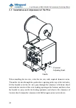
2.3.1 Clearance Adjustment Methods
(1) Clearance adjustment methods in case of tin feeding:
①
When the tin wire of 0.3mm is used, rotate the adjusting screw
counterclockwise until the clearance of tin feeding wheel is minimum.
When you feel the adjusting screw is very loose and the force is not
required during rotation, the minimum clearance is reached. At this time,
rotate the adjusting screw clockwise. When you feel the required force is
increased, rotate the adjusting screw by 1/2 turn to 2/3 turn.
②
When the tin wire of 0.4mm is used, the adjustment method is the same as
that of the tin wire of 0.3mm.
③
When the tin wire of 0.5mm, 0.6mm, 0.8mm, 1.0mm or 1.2mm is used, it
is only necessary to adjust the clearance of tin feeding wheel to the
minimum clearance.
④
When the tin wire of 1.4mm or 1.5mm is used, the adjustment method is
the same as that of the tin wire of 0.3mm.
(2) Clearance adjustment methods in case of tin breaking:
①
When the tin wire of 0.6mm, 0.8mm, 1.0mm or 1.2mm is used, it is only
necessary to adjust the clearance of tin feeding wheel to the minimum
clearance.
②
When the tin wire of 1.4mm or 1.5mm is used, the adjustment method is
the same as that of the tin wire of 0.3mm.
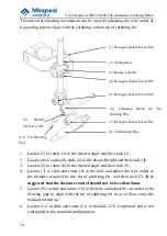
2.3.2 Service Life of Tin Breaking Blade
1. Force bearing mode of blade
The maximum penetrating depth of the blade is 0.75mm (The maximum
diameter of tin wire is 1.5mm), and the whole depth of the blade is 2.7mm. As
shown in the figure below, the main force bearing part is the tooth tip, which is
a part easy to wear on the blade and is a main factor influencing the service life.


