


2
2
.
Name and function of each point
2-1.
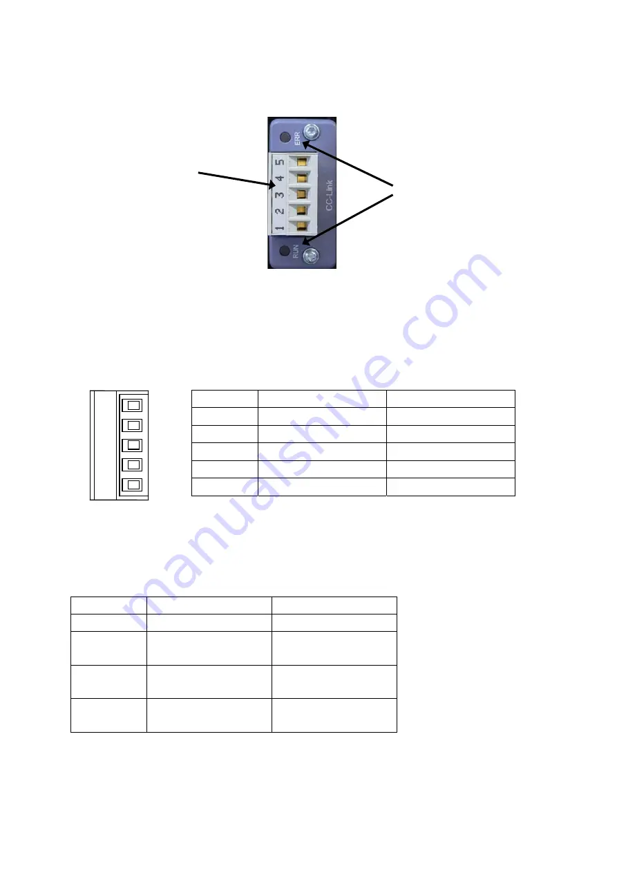
Rear panel for CC-Link I/F
(
1
)
Communication
connector
Connector type terminal block for CC-Link interface.
Connector pin configuration for communication
is as follows
※
Suitable plug : MSTB 2,5-ST-5,08 ABGY AU by PHOENIX CONTACT.
※
to be attached.
※
“SLD” and “FG" are connected inside.
※
The internal circuit and photo coupler are insulated.
(
2
)
Status LED
The communication status is expressed with two LED.
Status RUN
ERR
Light off
-
Normal
Green LED
Light on
Normal
-
Red LED
Light on
Hardware error
Hardware error
Red LED
Light on/off
-
CRC
error
Pin No.
Signal name
Contents
1
DA
Signal line DA side
2
DB
Signal line DB side
3
DG
Signal line ground
4 SLD
Shield
5 FG Frame
ground
DA
DB
DG
SLD
FG
1 2
3
4
5
(
2
)
Status LED
(
1
)
Communication connector


