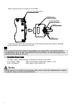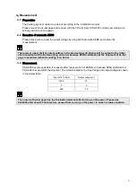
3
3-3.
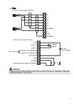
Wiring
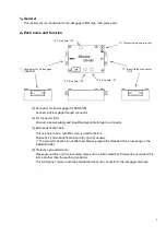
Connector for tie-bar gage (SENSOR)
Connector for input and output (I/O).
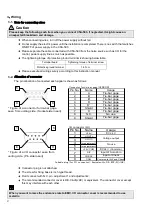
Caution
Please execute the wiring of external control input as shown in the figures. If neglected, it may cause
unexpected damage or misoperation.
A
E Shield
N.C.
C
E Shield
D’
D
B’
B
7
8
2
3
4
5
6
1
9
1
2
3
4
5
6
7
8
9
+24 V
V-OUT +
V-OUT -
Terminal 1 for adjustment
+24 V COM.
A/Z
CHECK
COM (for input of A/Z and CHECK)
Terminal 2 for adjustment
Don’t connect.
or
Voltage
output
DC24 V
Power supply
V
Summary of Contents for CSA-593
Page 2: ......
Page 9: ...VIII 9 WARRANTY AND REAPIR 12 9 1 WARRANTY 12 9 2 REPAIR 12 ...
Page 10: ...VI ...
Page 23: ... ...


