4
Product Overview
1. AC Power Input
2. USB Connectors
They connect such devices as the USB mouse, USB
keyboard, etc.
3. Nurse Call Connector
It connects the patient monitor to the hospital’s nurse call system
through the nurse call cable (PN: 8000-21-10361). Alarms
indications are alerted to nurses through the nurse call system, if
configured to do so.
4. Micro-D Connector
It outputs ECG, IBP and defibrillator synchronization signals
simultaneously.
5. Network Connector
It is a standard RJ45 connector that connects the patient
monitor to the CMS or other devices through the LAN.
6. iView Network Connector
It is a standard RJ45 connector that connects the iView system to
external network.
7. USB connector
They connect the controlling devices (USB mouse and USB
keyboard) of the secondary display.
8. Digital Video Interface (DVI)
It connects a standard digital video display.
9. SMR Connector
It connects the satellite module rack (SMR).
10. USB Connectors
They are only used for iView maintenance and data transfer.
11. Equipotential Grouding Terminal
When the patient monitor and other devices are to be used
together, their equipotential grounding terminals should
be connected together, eliminating the potential difference
between them.
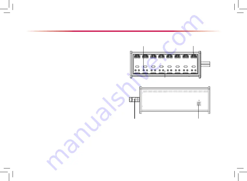
Satellite Module Rack
Contact
Indicator
SMR connector
Handle
As shown in the figure above, there is an indicator telling the
status of the SMR:
On: when the SMR works normally.
Off: when the SMR disconnects from the patient monitor, there is a
problem with the power, or the patient monitor shuts down.
The SMR can be connected to the patient monitor through their
SMR connectors via a SMR cable.
Slot


