


4
status lights located beside the screen will change color.
In addition, if you have enabled Wi-Fi and subscribe to the
interface portal, the unit will send out your choice of emails or
text messages, or both, to notify you of alerts. See “Setting up
Wi-Fi” section for details on connecting to the interface portal.
In the next instructions, you will learn how to set pH values to
activate Caution and Critical Alerts. A Caution is intended to
alert you when the pH value has deviated too far from your
setpoint. A Critical alert is to let you know that the pH value has
deviated even further and you have a serious problem needing
immediate attention.
It is your responsibility to set the pH alert parameters for your
specific requirements. This is a balancing act and may require
some experimentation on your part. You do not want the pH value
to drift too far from your setpoint without an alert, but you also
don’t want the DL122 to be sending you alerts too frequently.
For most applications, Milwaukee Instruments recommends
a minimum .7 difference between the setpoint and a Caution
alert; and a minimum 1.4 difference between the setpoint and
a Critical alert.
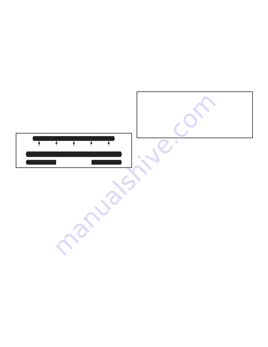
See the diagram below.
5.60 6.30 7.00 7.70 8.40
Critical Caution Setpoint Caution Critical
Red | Lime | Blue | Lime | Red
Below Alert
Above Alert
If the value for pH is within the Caution parameters you have set,
the status lights on both sides of the screen will remain blue.
If the blue changes to lime, this signals that the value has
reached the Caution level. If the reading continues to drift
further from the setpoint and reaches the Critical level, the lime
lights will turn red, indicating a critical condition.
Setting pH Below Alerts (Caution & Critical)
Menu Button>pH>pH Below Alert
1) Work your way to the *pH Below Alert* screen. You will see
two options: “pH Caution” and “pH Critical.” If the settings shown
beside each are the desired settings, you may “Exit” the screen.
2) If you want to change the Caution setting, place the cursor
beside “pH Caution” and press SELECT.
3) On this screen, use the keypad arrows to create the new
setting, and press SELECT. The SAVED! screen will appear and
you will be taken back to the *pH Below Alert* screen.
4) Move the cursor to the “pH Critical” option; press SELECT,
then enter the new setting.
5) Press SELECT and you have completed the setup for the pH
Below Alerts. Scroll down and select “Exit” to go back to **pH
Menu** screen or press Menu button to go back to primary
display screen.
Setting pH Above Alerts (Caution & Critical)
Menu Button>pH>pH Above Alert
1) Work your way to the *pH Above Alert* screen. You will see
two options: “pH Caution” and “pH Critical.” If the settings shown
beside each are the desired settings, you may “Exit” the screen.
2) If you want to change the Caution setting, place the cursor
beside “pH Caution” and press SELECT.
3) On this screen, use the keypad arrows to create the new
setting, and press SELECT. The SAVED! screen will appear and
you will be taken back to the *pH Above Alert* screen.
4) Move the cursor to the “pH Critical” option; press SELECT,
then enter the new setting.
5) Press SELECT and you have completed the setup for the pH
Above Alerts. Scroll down and select “Exit” to go back to **pH
Menu** screen or press Menu button to go back to primary
display screen.
IMPORTANT: When pH settings have been entered and
saved, plug the controller power box into a 120VAC wall
socket or power supply. Note that pH devices to be controlled
by pH value readings must be plugged into the top socket.
IDC devices must be plugged into the bottom socket. The
red indicator lights beside the pH and IDC sockets, labeled
“Activated,” let you know when the sockets are providing
power to the devices.
Setting Manual Temperature
Compensation
Menu Button>pH>Manual Temp. Comp.
Work your way to the *Manual Temperature Compensation*
screen. Using left/right arrows to scroll blinking cursor through
temperature and up/down arrows to change numbers, enter
the temperature of your solution, being sure to note if it is set
for Fahrenheit or Celsius scale. When complete, press SELECT
and the SAVED! screen will appear.
When manual temperature compensation has been set, MRC will
appear in the lower right corner of the primary display screen.
Setting pH Hysteresis
Menu Button>pH>pH Hysteresis
To prevent excessive on/off cycling of dosing devices, the “pH
Hysteresis” feature allows you to customize the lag (delay)
in device activation. Without hysteresis, your controller will
attempt to correct even the slightest variation in pH value and
will be cycling on and off almost continuously.
On the **pH Hysteresis** screen, you may select from four pH
options: 0.500, 0.100, 0.050, and 0.005. Place the cursor beside
your selection, press SELECT and the SAVED! screen will
appear. The default setting for this unit is pH 0.050.
As an example, if your setpoint is 6.5 (Set for ABOVE) and you set
hysteresis at 0.050, then the controller will activate your dosing
device when the pH value reaches 6.550 and will continue dosing
until the pH value returns to 6.450.
Setting up the Data Logger
(Time Interval & Start Time)
Please note that if you remove the SD card when the unit is ON,
the unit will remain operational. However, before re-inserting
the SD card, disconnect the unit from its power source. Once


