background image

5

you have the SD card snapped back in place, restore power 

to the unit. If you re-insert the SD card while the unit is 

operational, you must still momentarily disconnect from power, 

then reconnect, allowing the unit to properly communicate 

with the SD Card. 
Also note that the internal SD card is fixed at two-minute 

logging intervals. The following instructions refer to the portal 

only. 

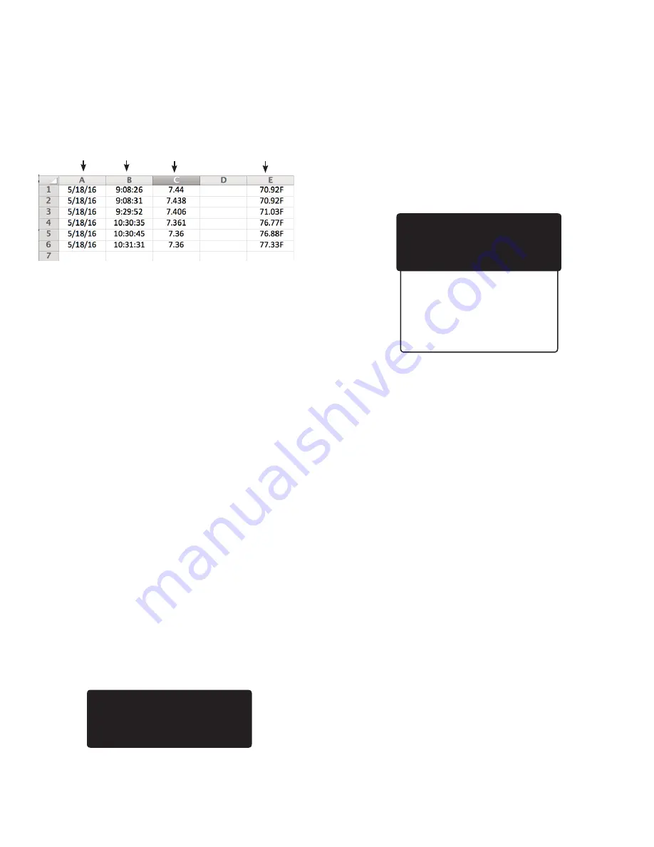
Example of Logged Data on SD Card

  Menu Button>Data Log Setup>Data Logger

1) Work your way to the **Data Logger** screen. The cursor will

appear beside “Set Time Interval.” Press SELECT.
2) On the “Set time interval” screen, using the keypad

arrows, enter the amount of time between logs, in Hours:

Minutes:Seconds (00:00:00). Logging is restricted to a 5-minute

minimum upload interval (except for Snap Shots); however,

Milwaukee Instruments recommends a wider interval,

typically 00:10:00 to 00:15:00. For most applications, this 10- to

15-minute interval is frequent enough to gather meaningful

data without collecting too much data, which can often make

evaluation cumbersome.
3) Press SELECT to save this interval. Screen will read SAVED!

and go back to the **Data Logger** screen with the cursor

beside “Start Time.”
4) Press SELECT to advance to the Start Time screen. Using the

keypad arrows, enter the start time and press SELECT to save.
5) Press the Menu button to return to the primary display screen.
Note: To capture a real-time reading, press the Snap Shot button. 

A snap shot will not interfere with scheduled data logging. When 

you press the Snap Shot button on the keypad, “Snap Shot” will 

appear for a few seconds in the lower right corner of the screen, 

indicating the real-time data has been logged.

Checking Last Logged Screen

Place cursor beside “Last Logged” and press SELECT. The **Last 

Logged** screen will appear. Press Menu button to return to 

primary display screen. 

Setting up Wi-Fi

In addition to displaying real-time data, the Wi-Fi and portal 

provide email and text alerts, store redundant data, and offer 

remote control of unit.
Use of Wi-Fi and portal is optional; it is not required. Not utilizing 

the portal will not affect operation of the unit. 
Your DL Controller is set up to transmit in the 2.4GHz frequency 

range only. If you are using a wireless router with two or more 

channels, please be sure to enter the “Network Name / SSID” that 

will access the 2.4GHz frequency channel only. The unit will not 

communicate at 5.0GHz.
Before beginning Wi-Fi setup, make sure you have the following:

• Wi-Fi Network Security Type (Open, WEP, or WPA)

• Wi-Fi Name, and

• Wi-Fi Password

IMPORTANT: Although “Wi-Fi Enable” is the first option listed, 

you should enter all Wi-Fi information with the unit in Wi-Fi 

Disabled mode. Enable Wi-Fi as the last step, otherwise the unit 

may begin uploading information before you finish entering it.

  Menu Button>Wi-Fi Settings>Wi-Fi Enable

1) Work your way to the **Wi-Fi Enable** screen.
2) On the **Wi-Fi Enable** screen, place cursor beside “Enable” 

and press SELECT.
3) Use the same procedure to Disable Wi-Fi.

  Menu Button>Wi-Fi Settings>Security Type

1) Work your way to the **Wi-Fi Security** screen and press

SELECT.
2) On the **Wi-Fi Security** screen, you will have the following

options: Open, WEP, and WPA. WPA is the most common. Place

cursor beside the appropriate security type and press SELECT.

    Menu Button>Wi-Fi Settings>Network Name/SSID

(Remember to use 2.4 GHz only)

1) Work your way to the “Network Name/SSID” screen and press

SELECT.
2) When the “Network Name/SSID” screen opens, fill in your Wi-

Fi name using the keypad arrows, and press SELECT.
  Menu Button>Wi-Fi Settings>Pre-shared Key (Password)

1) Work your way to the **Pre-shared Key** screen and press

SELECT.
2) When the screen opens, the heading will read “Network

Password.” 
3) Fill in your Wi-Fi password using the keypad arrows, and

press SELECT.

**    Last Logged    **

01/05/16        08:06:07

pH: 7.105

Temperature:   77.56º F    

 **   Wi-Fi Settings   **

> Wi-Fi Enable

Security Type

Network Name/SSID

Pre-shared Key

View Device IP

Upload Interval

Portal Sync

Portal Service

Exit

    Date          Time             pH

Temperature

Summary of Contents for DL122

Page 1: ...1 DL122 BLACK BOX DATA LOGGING CONTROLLER pH Temperature Set Up Operation Manual Test Equipment Depot 800 517 8431 99 Washington Street Melrose MA 02176 TestEquipmentDepot com ...

Page 2: ...H Below Alert pH Above Alert Manual Temp Comp pH Hysteresis Exit Probe Diagnostic Follow Instructions Given Here Menu Basic Setup pH Data Log Setup Last Logged Wi Fi Settings IDC Setup Exit Menu Basic Setup pH Data Log Setup Last Logged Wi Fi Settings IDC Setup Exit Last Logged 01 05 16 08 06 07 pH 7 00 Temperature 22 56º C Wi Fi Settings Wi Fi Enable Security Type Network Name SSID Pre shared Key...

Page 3: ...mpensation will appear in the lower right portion of screen If not MTC Manual Temperature Compensation will display On the menu screens only four lines will be visible at a time To see more options scroll the list by using up down arrows on the keypad When the cursor appears beside the appropriate function or setting press SELECT THE KEYPAD Pressing the Menu button brings up a screen featuring the...

Page 4: ...utes 00 00 using left right arrows picking the number you want to change then using up down arrows to select the appropriate number Note that this unit displays in military time 24 hour there is no am pm option that is 9AM is 09 00 and 2 05PM is 14 05 10 30PM is 22 30 9 Once complete press SELECT to enter the new time A screen will appear indicating that your change has been SAVED 10 Scroll to Exi...

Page 5: ...2 105 A 3 point calibration will always give you an acid and a base slope however when using 1 or 2 point calibration depending on points chosen you may get an acid OR a base slope reading In this case the other reading will show as a default 99 9 pH Probe Diagnostic Menu Button pH pH Probe Diagnostic pH probes have a limited lifetime and must be replaced periodically to maintain accurate readings...

Page 6: ...pH pH Above Alert 1 Work your way to the pH Above Alert screen You will see two options pH Caution and pH Critical If the settings shown beside each are the desired settings you may Exit the screen 2 If you want to change the Caution setting place the cursor beside pH Caution and press SELECT 3 On this screen use the keypad arrows to create the new setting and press SELECT The SAVED screen will ap...

Page 7: ...a the Wi Fi and portal provide email and text alerts store redundant data and offer remote control of unit Use of Wi Fi and portal is optional it is not required Not utilizing the portal will not affect operation of the unit Your DL Controller is set up to transmit in the 2 4GHz frequency range only If you are using a wireless router with two or more channels please be sure to enter the Network Na...

Page 8: ...time that is available the message on your screen will read Please enter a valid number of sessions per day You will need to enter a lower number of Sessions Per Day or make adjustments in Start End times and or Session Time Menu Button IDC Setup Session Time Session Time is the length of time duration that your device will be turned on All session times must be the same length 1 Press Menu button...

Page 9: ...ubing diameter and many other factors play a role in how long your pump should run the DL122 is equipped with a flow calibration feature 1 Press Menu button scroll down to IDC Setup and press SELECT 2 Place cursor beside Flow Calibration and press SELECT 3 Be sure the cursor is beside START Using a container of appropriate size or one marked with an appropriate fill level place the tube from the p...

Page 10: ...8 ...

Page 11: ...9 ...

Page 12: ...ock S Ram 96 KBytes of SRAM two banks 64KB and 32KB Flash Memory 512 KB Data Retention 100 years at 25 C Station and Access Point Wi Fi 802 11 b g n Roles with Integrated Radio Baseband and MAC TCP IP Embedded TCP IP stack Circuit Board Protection RJ45 Back Feed Protection with Short Circuit Protection GLP Ground Loop Prevention Dual Ground Loop Prevention Circuit and Chipset Input Power Supply 7V...

Reviews: