


4
Setting pH Below Alerts (Caution & Critical)
Menu Button>pH>pH Below Alert
1) Work your way to the *pH Below Alert* screen. You will see
two options: “pH Caution” and “pH Critical.” If the settings shown
beside each are the desired settings, you may “Exit” the screen.
2) If you want to change the Caution setting, place the cursor
beside “pH Caution” and press SELECT.
3) On this screen, use the keypad arrows to create the new
setting, and press SELECT. The SAVED! screen will appear and
you will be taken back to the *pH Below Alert* screen.
4) Move the cursor to the “pH Critical” option; press SELECT,
then enter the new setting.
5) Press SELECT and you have completed the setup for the pH
Below Alerts. Scroll down and select “Exit” to go back to **pH
Menu** screen or press Menu button to go back to primary
display screen.
Setting pH Above Alerts (Caution & Critical)
Menu Button>pH>pH Above Alert
1) Work your way to the *pH Above Alert* screen. You will see
two options: “pH Caution” and “pH Critical.” If the settings shown
beside each are the desired settings, you may “Exit” the screen.
2) If you want to change the Caution setting, place the cursor
beside “pH Caution” and press SELECT.
3) On this screen, use the keypad arrows to create the new
setting, and press SELECT. The SAVED! screen will appear and
you will be taken back to the *pH Above Alert* screen.
4) Move the cursor to the “pH Critical” option; press SELECT,
then enter the new setting.
5) Press SELECT and you have completed the setup for the pH
Above Alerts. Scroll down and select “Exit” to go back to **pH
Menu** screen or press Menu button to go back to primary
display screen.
Setting Manual Temperature
Compensation
Menu Button>pH>Manual Temp. Comp.
Work your way to the *Manual Temperature Compensation*
screen. Using left/right arrows to scroll blinking cursor through
temperature and up/down arrows to change numbers, enter
the temperature of your solution, being sure to note if it is set
for Fahrenheit or Celsius scale. When complete, press SELECT
and the SAVED! screen will appear.
When manual temperature compensation has been set, MRC will
appear in the lower right corner of the primary display screen.
Setting up the Data Logger
(Time Interval & Start Time)
Please note that if you remove the SD card when the unit is ON,
the unit will remain operational. However, before re-inserting
the SD card, disconnect the unit from its power source. Once
you have the SD card snapped back in place, restore power
to the unit. If you re-insert the SD card while the unit is
operational, you must still momentarily disconnect from power,
then reconnect, allowing the unit to properly communicate
with the SD Card.
Also note that the internal SD card is fixed at two-minute
logging intervals. The following instructions refer to the portal
only.
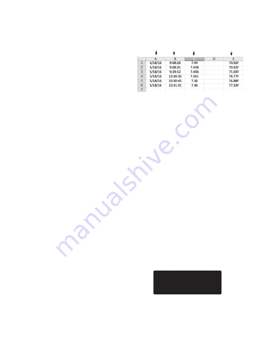
Example of Logged Data on SD Card
Menu Button>Data Log Setup>Data Logger
1) Work your way to the **Data Logger** screen. The cursor will
appear beside “Set Time Interval.” Press SELECT.
2) On the “Set time interval” screen, using the keypad
arrows, enter the amount of time between logs, in Hours:
Minutes:Seconds (00:00:00). Logging is restricted to a 5-minute
minimum upload interval (except for Snap Shots); however,
Milwaukee Instruments recommends a wider interval,
typically 00:10:00 to 00:15:00. For most applications, this 10- to
15-minute interval is frequent enough to gather meaningful
data without collecting too much data, which can often make
evaluation cumbersome.
3) Press SELECT to save this interval. Screen will read SAVED!
and go back to the **Data Logger** screen with the cursor
beside “Start Time.”
4) Press SELECT to advance to the Start Time screen. Using the
keypad arrows, enter the start time and press SELECT to save.
5) Press the Menu button to return to the primary display screen.
Note: To capture a real-time reading, press the Snap Shot button.
A snap shot will not interfere with scheduled data logging. When
you press the Snap Shot button on the keypad, “Snap Shot” will
appear for a few seconds in the lower right corner of the screen,
indicating the real-time data has been logged.
Checking Last Logged Screen
Place cursor beside “Last Logged” and press SELECT. The **Last
Logged** screen will appear. Press Menu button to return to
primary display screen.
Setting up Wi-Fi
In addition to displaying real-time data, the Wi-Fi and portal
provide email and text alerts, store redundant data, and offer
remote control of unit.
Use of Wi-Fi and portal is optional; it is not required. Not utilizing
** Last Logged **
01/05/16 08:06:07
pH: 7.105
Temperature: 77.56º F
Date Time pH Temperature


