


TM-357 Page 14
Dynasty DX
SECTION 5 – PRE-POWER CHECKLIST
5-1.
Checking Unit Before Applying Power
.
See Section 6-2 for test points and values and Section
10 for parts location.
Y
Discharge input capacitors according to Section 7-5 and be sure voltage is near zero before touching any parts.
Y
Before troubleshooting or applying power to unit, complete following checks to avoid causing further damage.
Y
Although control board PC1 and hall device HD1 are briefly checked in this procedure, more complete tests may be needed later for
these parts. This check is simply to get a basic okay to power up unit.
5-2.
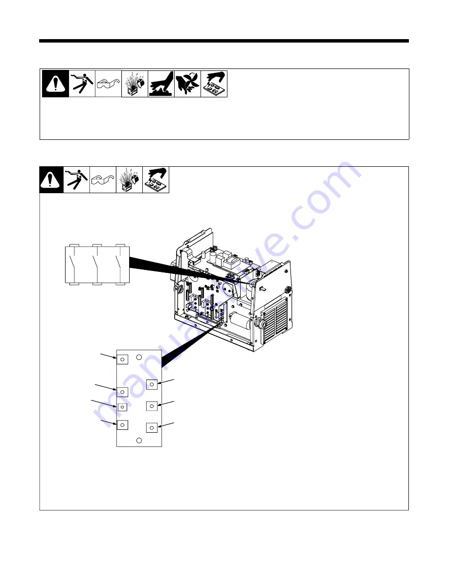
Input Rectifier SR1
ST-801 550 / Ref. SD-183 484
Y
Read and follow safety
information in Section 5-1
before proceeding.
.
Resistance values are based
on in-circuit measurements.
1
Visually inspect SR1 for
damage.
2
Check 6 diodes (diode test).
Check from each ac terminal
to the positive (+) terminal and
from each ac terminal to the
negative (–) terminal.
3
Check precharge SCR (ohms
position). Connect negative
lead to SCR (–) terminal and
positive lead to positive (+)
terminal. Resistance should
be 200 ohms
±
10%. Connect
a jumper between positive (+)
and gate terminals.
Resistance should be
approximately 35 ohms.
4
If results are in doubt, use an
IGBT tester (MILLER Part No.
043 553) to test the SCR
portion of SR1 as follows:
A. Disconnect plug PLG13
from receptacle RC1 on in-
terconnecting board PC2.
B. Connect red clip to positive
(+) terminal.
C. Connect black clip to SCR
(–) terminal.
D. Connect yellow clip to gate
terminal.
5
If SR1 is defective, check the
three poles of power switch
S1 (switch off = OL, switch on
= 0 ohms).
Input Rectifier SR1
Gate
SCR (–)
AC (L3)
AC (L2)
AC (L1)
Positive (+)
Negative (–)
Power Switch S1
–
+
G
R2
T
S
R
Summary of Contents for DYNASTY DX
Page 27: ...TM 357 Page 25 Dynasty DX Notes...
Page 47: ...TM 357 Page 45 Dynasty DX SD 183 036 C...
Page 49: ...TM 357 Page 47 Dynasty DX SD 189 922...
Page 51: ...TM 357 Page 49 Dynasty DX SD 183 037 B...
Page 53: ...TM 357 Page 51 Dynasty DX SD 183 732 A...
Page 55: ...TM 357 Page 53 Dynasty DX SD 183 732 A...
Page 57: ...TM 357 Page 55 Dynasty DX SD 183 732 A...
Page 59: ...TM 357 Page 57 Dynasty DX Notes...
Page 61: ...TM 357 Page 59 Dynasty DX SD 189 540...
Page 63: ...TM 357 Page 61 Dynasty DX SD 189 540...


