background image

4K IP Streaming Extender


5. Operation of IPA Manager 

5.1 General Information 

The IPA Manager is a demonstration control software used to configure and control 
signal extension, routing and switching between   MP-IP300TR units. 

The IPA Manager includes Web GUI version and Windows PC version. 

The control PC can be connected to the ETHERNET port of any device or to any RJ45 
port of the 10GbE switch except the management/console port of the switch which is 
not part of the network. 

Before proceeding, make sure all the units are powered ON. Then ensure that the IP 
addresses of PC and all the units are on the same local area network (LAN).   

Start the application by double clicking on

 IPA Manager.exe

 file. If you receive a pop-

up asking for network access confirmation, make sure that both Private and Public 
networks are allowed. 
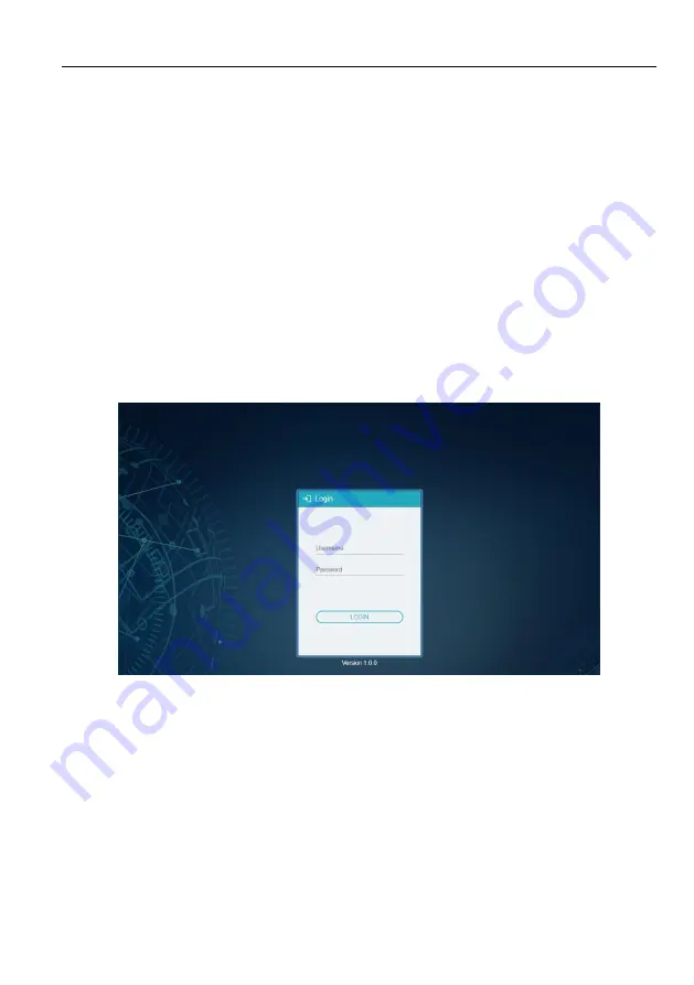
 

Username: 

admin 

Password: 

admin 

Please type the username and password, and then click 

Login

.   


Upon launch, the IPA Manager

’s main interface will appear as showed in the picture 

below: 

Summary of Contents for MP-IP300TR

Page 1: ...MP IP300TR 4K IP Streaming Transceiver All Rights Reserved Version MP IP300TR_2021V1 0 User Manual...

Page 2: ...Statement This equipment generates uses and can radiate radio frequency energy and if not installed and used in accordance with the instructions may cause harmful interference to radio communications...

Page 3: ...ure or install this product near water Do not put any heavy items on the extension cable in case of extrusion Do not remove the housing of the device as opening or removing housing may expose you to d...

Page 4: ...Information 9 5 2 Device Configuration 10 5 3 Start IPA Manager 11 5 4 Video Routing Tab 12 5 4 1 Video Switching 13 5 4 2 Sending Single Source to All RX Devices 13 5 4 3 Stopping Starting Video 14...

Page 5: ...tings 26 5 9 1 Receiver RX Settings Options 26 5 9 1 1 Display EDID 26 5 9 1 2 Network Setting 27 5 9 1 3 RS232 28 5 9 2 Transmitter TX Settings Options 29 5 9 2 1 Input 29 5 9 2 2 Device EDID 29 5 9...

Page 6: ...er 10 Gigabit Ethernet in enterprises and other large scale installations 1 1 About 10G Network Unlike traditional AV extension technology such as HDBaseT where transmitters and receivers are connecte...

Page 7: ...Broadcast IPV4 protocol or local control by API server MP IP300TR series are configurable HDCP 2 2 compliant Supports arbitrary Multi view layout Supports Video Wall mode up to 5x5 screens Selectable...

Page 8: ...DMI Video Output Connector 1 Type A female HDMI HDMI Output Resolution Up to 4Kx2K 60Hz 4 4 4 8bit General Control 1 10G LAN 1 IR IN 1 IR OUT 1 RS232 1 ETHERNET Control Connector 2 RJ45 2 3 5mm jack 1...

Page 9: ...table video signal is detected ETHERNET LED The LED illuminates if data are transmitted LED on Packets are not transmitted LED blinking Packets are transmitted HDMI IN LED The LED illuminates green wh...

Page 10: ...or a network switch using a CATx cable IR IN 3 5mm jack to connect an IR receiver for IR routing control IR OUT 3 5mm jack to connect an IR emitter for IR routing control RS232 3 pin terminal block f...

Page 11: ...Point to Point In a point to point configuration there is no need for a switch Distribute full uncompressed data up to 4K 60Hz 4 4 4 resolution as well as 1G Ethernet audio and control signals over a...

Page 12: ...4K IP Streaming Extender 7 4 3 System Diagram The following diagram illustrates typical input and output connections that can be utilized with the MP IP300TR Matrix System...

Page 13: ...or RX 7 Optional Connect compatible IR receiver modules to the IR input connectors of any TX or RX 8 Connect a 10G Ethernet cable Cat 6a recommended from the 10GbE port each TX and RX unit to any ava...

Page 14: ...ept the management console port of the switch which is not part of the network Before proceeding make sure all the units are powered ON Then ensure that the IP addresses of PC and all the units are on...

Page 15: ...open up in the Video Switching tab It will discover all the devices on the network and display them inside the application All connected devices on the network will appear as gray tiles within the ap...

Page 16: ...mber of 6970 The Control Server currently only listens to port 6970 After connecting to the Control Server the IPA Manager will show discovered devices as tiles There are few things to take note of Th...

Page 17: ...lay is genlocked to the source as if it is directly connected In cases of the input video having a too large bandwidth to fit into a 10G network link e g 4K 60Hz 4 4 4 the video is slightly compressed...

Page 18: ...g displayed please verify the following Ensure that the network switch has been properly configured Confirm that the display can support the input source resolution Verify that the HDMI cable being us...

Page 19: ...tive Transmitter TX and select Start Video 5 4 4 Disconnecting Source from RX To disconnect a Receiver RX from a Transmitter TX source right click the gear icon of the respective RX tile and select Le...

Page 20: ...portion is reserved for configuring and setting up the video wall while the bottom half lists all available TX Transmitter and RX Receiver units The video wall size can be adjusted by changing the nu...

Page 21: ...3 Next drag the desired Transmitter TX source tile and drop it onto the tile labeled TX Drop Here 4 The source will now be visible across the whole Video Wall matrix according to your configuration 5...

Page 22: ...xtender 17 To delete a preset select one and the click then delete icon to delete it To rename the desired preset select it and click the gear icon then type the new name in the textbox and click Y to...

Page 23: ...nd select the option Remove from Wall 5 5 4 Changing Output Resolution for Video Wall Receivers To control the receiver s output resolutions click the gear icon on the video wall selection Select Wall...

Page 24: ...4K IP Streaming Extender 19...

Page 25: ...gure below illustrates the Multi View routing tab inside the IPA Manager The top portion is reserved for selecting Multi View mode while the bottom half is for selecting TX Transmitter and RX Receiver...

Page 26: ...ransmitters TX and Receivers RX Each device discovered on the network is listed in both groups because each can both send and receive RS 232 data 1 Select the RS 232 Routing tab in the IPA Manager int...

Page 27: ...the tile labeled All Displays in the Receivers section of the RS 232 Routing tab 5 7 2 Sending RS 232 Data from IPA Manager to a Device 1 Click gear icon of the respective transmitter or receiver til...

Page 28: ...ive IR data 1 Select the Infrared Routing tab in the IPA Manager interface 2 Verify which Transmitters and Receivers are joined together Left click on the device tile where you want to see the connect...

Page 29: ...ile onto the tile labeled All Displays in the Receivers section of the RS 232 Routing tab 5 8 2 Sending IR Data from IPA Manager to a Device 1 Click gear icon of the respective transmitter or receiver...

Page 30: ...ples http www remotecentral com features irdisp1 htm The pronto format is a series of hex numbers that describe everything that is needed to generate the required waveform It includes the carrier freq...

Page 31: ...Switching etc 5 9 1 Receiver RX Settings Options The following section illustrates the Receiver RX device settings dialog box 5 9 1 1 Display EDID Use this tab to access and store the EDID coming from...

Page 32: ...e IP address can be set to be either DHCP or Manual Select DHCP to receive the IP address from a DHCP server or to be auto assigned with an IP from the 169 254 X X range in case there is no DHCP serve...

Page 33: ...2 tab to modify edit the RS232 settings Select the desired port configuration Baud Rate Data Bit Stop Bit and Parity Click the Save button to save the updated RS232 configuration New RS232 settings ar...

Page 34: ...s disabled streaming a video from an HDCP protected source to a screen will result in a black image displayed on screen It is also possible to only enable HDCP 1 4 by checking the Disable HDCP 2 2 sup...

Page 35: ...The IP address can be set to either DHCP or Manual Select DHCP to receive the IP address from a DHCP server or to be auto assigned an address within the 169 254 X X range in case there is no DHCP ser...

Page 36: ...ent Tab 5 10 1 Device Firmware Upgrade Apply device firmware updates directly over the network IPA has implemented a special update protocol to update an individual device or consecutively update all...

Page 37: ...ays them as orange bars Devices not available on the network earlier will be shown as DISCONNECTED 4 Begin the update process To trigger the upgrade of an individual device click the gear icon on the...

Page 38: ...ckup to save the system configuration data into the specified file 4 Click Browse on the Restore tile to select the backup file and click Restore Backup to restore the selected system configuration 5...

Page 39: ...5 10 4 System Logs Select the System Logs tab in the IPA Manager interface to enter the section for inquiring the system logs 5 11 Routing Table The routing table allows to gather info about the vide...

Page 40: ...4K IP Streaming Extender 35 Video Routing Table RS232 Routing Table...

Page 41: ...4K IP Streaming Extender 36 Infrared Routing Table...

Page 42: ...e type the user name and password and then click LOGIN Before starting the GUI control make sure the control PC is connected either directly to the network switch or to the Gigabit Ethernet port on on...

Page 43: ...4K IP Streaming Extender 38 7 Panel Drawing MP IP300TR...

Page 44: ...same network Please make sure each device has a different IP address in the same LAN Power supply is normal and as specified The connection cables are of high quality and the link has been establishe...

Page 45: ...ar Use of supplies or parts not meeting our specifications No certificate or invoice as the proof of warranty The product model showed on the warranty card does not match with the model of the product...

Reviews: