


All images shown in the manual are for illustration purpose only.
Introduction
5
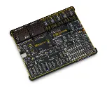
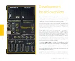
Development board overview
6
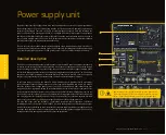
Power supply unit
8
Detailed description
8
ADC INPUT
9
Voltage reference
9
Programming voltage
9
PSU connectors
10
Power/debug, USB-C connector
10
Power 12VDC, external power supply
10
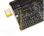
Battery power supply
11
Power redundancy and uninterrupted power supply (UPS)
12
Powering up the development board
12
Dual power supply
12
CODEGRIP – programmer/debugger module
14
Device setup
15
PGC/PGD jumpers
15
DBG selection
15
Connectivity 16
MCU sockets
18
How to properly install the MCU into the DIP socket?
19
Crystal oscillator
19
INPUT/OUTPUT section
20
PORT buttons
20
BUTTONS PRESS LEVEL
20
UP-PULL-DOWN switch
20
PORT LEDs
20
2x5 pin headers
21
1x20 GLCD graphical display connector
22
1x16 LCD character display connector
25
mikroBUS
™
sockets
26
Click boards
™
27
Communication 28
USB-UART
28
CAN
28
LIN COMMUNICATION
29
USB 30
Additional GNDs
31
What’s Next?
34
T
able of cont
ent
s


