


E a s y P I C v 8 f o r P I C 2 4 / d s P I C 3 3
M a n u a l
P A G E 29
1
9
5
4
10
16
15
3
2
7
6
8
11
13
18
17
P A G E 29
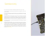
COMMUNICA
TION
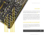
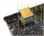
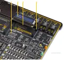
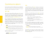
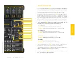
Figure 14: Main board partial right side view
LIN COMMUNICATION
LIN (Local Interconnect Network)
(13)
is a inexpensive serial network protocol used for
communication between components in vehicles, It effectively supports remote application
within a car's network. The LIN Bus is particularly intended for mechatronic nodes in
distributed automotive applications, but is equally suited to industrial applications.
The EasyPIC v8 for PIC24/dsPIC33 utilizes the MCP2003B
(14)
, it provides a physical interface
to automotive and industrial LIN systems, in accordance to the LIN Bus Specifications
Revision 2.2, SAE J2602 and ISO 17987. It is short circuit and overtemperature protected
by internal circuitry. MCP2003B communicates with the target board MCU through the
UART interface (RXD, TXD), with additional functionality provided by the CS and WAKE pins.
LIN connectivity is provided only for MCUs installed in DIP28C and DIP40B MCU sockets.
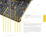
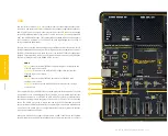
A six-pole DIP switch SW8
(15)
located in the LIN COMM, section of the board, allow fully
independent control of the UART RX and TX lines, and CS and WAKE lines.
SW8.1/SW8.2 (TX)
ON (up):
connects the RB0 and RB7 pins to the transmit data input
OFF (down):
disconnects the RB0 and RB7 pins from the transmit data input
SW8.3/SW8.4 (RX)
ON (up):
connects the RB1 and RB2 pins to receive data output
OFF (down):
disconnects the RB1 and RB2 pins from the receive data output
SW8.5 (CS)
ON (up):
connects the RB14 pin to the chip select input
OFF (down):
disconnects the RB14 pin from the chip select input
SW8.6 (WK)
ON (up):
connects the RB15 pin to the wake up input
OFF (down):
disconnects the RB15 pin from the wake up input
A jumper resistor marked as CS SEL
(16)
, allows the connection of the CS pin to the
dedicated MCU pin, or to a board power supply through a 4.7k pull-up resistor.
A jumper resistor marked as L-PULL
(17)
, allows the connection of external voltage supply
to LIN Bus, or can be removed if external supply is not necessary.
On-board screw terminal CN16
(18)
is used to provide an easy connection of the transceiver
to a LIN network (three wires: LBUS, VBB and GND).


