


P A G E 12
E a s y P I C v 8 f o r P I C 2 4 / d s P I C 3 3
M a n u a l
Power redundancy and uninterrupted
power supply (UPS)
The PSU module supports power supply redundancy: it will automatically switch to
the most appropriate power source if one of the connected power sources fails or
becomes disconnected. The power supply redundancy also allows for an uninterrupted
operation (e.g. UPS functionality, the battery will still provide power if the USB cable is
removed, without resetting the MCU during the transition period).
Powering up the development board
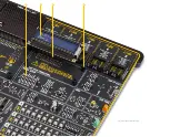
Two touch-sensitive buttons are used to power up and reset the EasyPIC v8 for
PIC24/dsPIC33 development board. These capacitive buttons are processed by two
AT42QT1011, digital burst mode charge-transfer sensors, specifically designed for
human-machine interfaces (HMI), from Microchip. The AT42QT1011 allows very
responsive and reliable touch detection for the connected button pad.
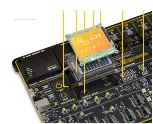
As soon as a valid power source is connected, the development board will enter the
Stand-By mode. When the capacitive POWER button is pressed, the PSU module will
start distributing the power to the rest of the development board. This is indicated by
the POWER LED indicator, located on the PSU module itself.
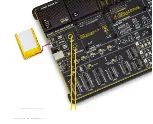
Right under the POWER LED, there is a CHARGE LED, indicating the charging status of
the Li-Po/Li-Ion single cell battery, if connected. The complete battery power supply
section, including the battery charger circuit, is explained in the respective chapter
of this manual.
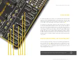
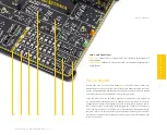
Below the POWER capacitive button
(1)
, there is a RESET capacitive button
(2)
which
is not entirely power-related, but it has a similar function: it is routed to the MCLR pin
of the MCU, allowing the RESET function to be performed.
P A G E 12
P O W E R S U P P L Y
Dual power supply
EasyPIC v8 for PIC24/dsPIC33 development board supports both 3.3V and 5V power
supply on a single board. Advanced PSU module provides the possibility to chose
power supply for board and host MCU, between 3.3V (default) and 5V. This setting
can be easily configured from CODEGRIP Suite, and this feature greatly increases the
number of supported MCUs.
To easily indicate the power supply configuration, the previously mentioned POWER
LED will also have a dual function. It lights up GREEN when 3.3V power supply is
configured, and lights up BLUE when 5V power supply is chosen.


